| Annotate tab > Dimensions group > |
| Annotate tab > Dimensions group > |
Geometric tolerances are used to indicate allowed geometric deviation of form, direction and location as defined in the drawing (ISO 1101). Tolerances are displayed in a tolerance frame. You can include two lines and a datum reference in a single tolerance frame.
There is a command line version as well as a dialog version of this function. The command line version is mainly used by application programs. You can also add a geometric tolerance to a leader object. The tolerance frame uses a font named GDT.ftf. The size of the tolerance frame is determined by the dimension text size and the value of the DIMGAP system variable. You can modify a tolerance object with the MODIFY command.
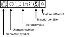
Tolerance object consists of a frame which contains a geometric symbol, one or two tolerance values, a material condition and 1-3 datum references. Tolerance is defined in a dialog.

Draw tolerances
Do the following:
-
Select the Tolerance function. The Geometric tolerance dialog opens.
-
Define the following:
-
Sym – Click the field to add a tolerance symbol.
 Show/hide details
Symbol
Type
Explanation

Location
Position

Concentricity

Symmetry

Direction
Parallelism

Perpendicularity

Angle

Form
Cylindrical

Flatness

Circularity

Straightness

Surface form

Line form

Run-out
Run-out

Total run-out
-
Tolerance 1 – First tolerance value
-
Tolerance 2 – Second tolerance value
-
Datum 1, Datum 2 and Datum 3 – You can define three datum references to a tolerance frame. Datum reference is usually a letter and you can also define a material condition to each datum reference separately.
-
Diam. – Click the field to add a diameter symbol.
-
MR – Click the field to add material conditions:
 Maximum material
condition (MMC)
 Least material
condition (LMC)
 Regardless of Feature Size (RFS), indicates
that the feature can be of any size within the set limits.
-
-
In the Projected tolerance zone section, define the following:
-
Click the Id field to add a projected tolerance zone identifier.
-
Define the height of the projected zone as well as a datum identifier.
-
-
Click OK.
Paste tolerances
With this function, you can define tolerances in the dimension styles or add tolerances to existing dimension objects.
Do the following:
-
Select dimension object.
-
Enter tolerance values (symbol, lower and upper values, and number of decimals).