| Single-line tab > Markings group > |
| Schematics tab > Markings group > |
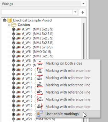
With the marking functions in the Cable menu, you can insert cable markings in your drawings. There
are several methods to mark the cables, to suit your requirements.
Marking on both sides or with reference lines
Do the following:-
Select Marking on both sides or Marking with reference line as the cable marking type.
Alternatively, start the function from the Wirings project tree by right-clicking Cables and selecting Cable marking.
-
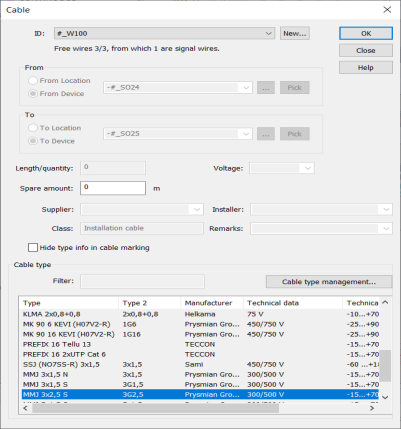
Enter information for the cable:
-
Select the ID of an existing cable from the drop-down list, or create a new cable by clicking New.
-
Select the From and To information from the drop-down menus, from the location tree by clicking the
 button or from the drawing by clicking Pick.
 -
You can define additional information, such as length, voltage or supplier, to their respective fields. Information found from the cable type is added automatically when a cable type is selected.
-
Hide type info is enabled when the project's cable marking setting Visibility of Type in drawing has been set to According to visibility setting of symbol's attribute. If the setting has been set to Always visible or Not visible, hiding is disabled.
-
Select the cable type from the project list. If you need a new cable type, click Cable type management, select the cable type and click Add to project.
-
- Click OK.
- Indicate the insertion point and angle.
Mark cable lines by picking
With this function, you can add cable marking to several cables one by one or simultaneously.
Do the following:
-
From the Cable menu, select Mark cable lines by picking or enter markingtocable to the command line.
-
Select Marking on both sides or Marking with reference line as the cable marking type.
After selecting the cable marking type, the cables are indicated in blue.
-
One by one, indicate the cables for which you want to add the selected marking. The markings are located to the center of the lines, and the angles are taken from the lines automatically.
Alternatively, enter intersection to the command line and then draw a line along multiple lines by indicating the start and end points of the intersecting line. The markings are then located to the intersection points.
Create your own cable markings
You can create your own cable markings.
Do the following:
-
From the Cable menu, select Save user cable marking.
-
Select the objects to include in the symbol to be saved, and confirm with Enter.
-
If the objects you selected did not include an ID attribute (E_ID), indicate insertion point for the symbol. The Save symbol dialog opens.
-
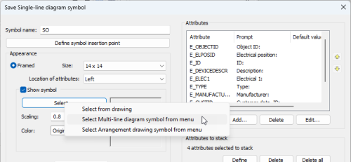
Define symbol information:
- Symbol name – Enter the name of the symbol to be saved. The function adds SO by default but you can name the symbols any way you want.
- Define symbol insertion point – Click to define insertion point.
- Appearance – The appearance can be framed or not framed. By default, the appearance is set to No Frame.
- Framed – The objects you selected after starting the function are added to the framed symbol.
There is a wiring point in the middle of each side of the frame. The top and bottom wiring points form a cut point pair, as well as the left and right wiring points.
The highest wiring point is the insertion point.
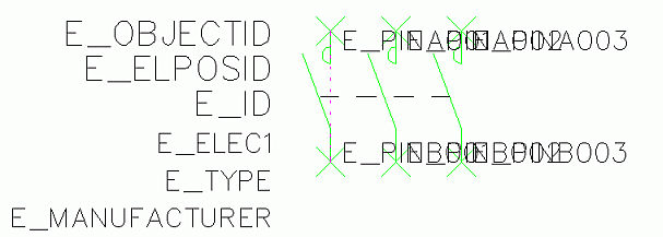
You can insert attributes inside the frame, to the right or left of the symbol, or above or below the symbol. Default attributes are located automatically. ID attributes are stacked automatically.
If you select Show symbol, you will see a preview of the symbol. In addition, with the Select button you can replace the objects you selected after starting the function with those you select from the drawing, from the multi-line diagram symbol menu or from the arrangement drawing symbol menu.
The objects you selected after starting the function are then removed, and the newly selected is added inside the frame.
- No Frame – With Select, you can replace the selected objects with those you select from the drawing, from the multi-line diagram symbol menu or from the arrangement drawing symbol menu. The objects you selected after starting the function are removed.
- Framed – The objects you selected after starting the function are added to the framed symbol.
- Wiring points –
-
Define – First, indicate the wiring point to which you want to draw the wiring. The point is marked with a cross. Second, pick wiring point's number attribute i.e. the attribute from which to read the connection information.
-
Delete – Pick the wiring point you want to remove. Removing a wiring point also removes cut points associated with it.
-
Delete all – Delete all wiring points defined to the symbol.
- Cut points –
-
Define:
-
Select 1. wiring point, which defines a cutting line: Select 1. wiring point (=cross) from the wiring point pair
-
Select 2. wiring point, which defines a cutting line: Select 2. wiring point (=cross) from the wiring point pair.
-
Function asks to select the next wiring point pair and marks the 1. wiring point pair with red dashed line.
-
-
Delete – Pick pair of cut points you want to remove. Cut points are marked with cross and dashed line.
-
Delete all – Removes all cut points from symbols wiring points.
- Symbol
data
- Symbol type is important for the functions to recognize the symbol to certain electric symbol.
-
The default symbol type is Other, and the default sub-type Single-line Diagram Symbol.
-
If you selected a symbol, the symbol type is set accordingly and Single-line Diagram Symbol will be set as the sub-type.
-
Symbol type is not included in the E_ID attribute.
- Select to create a horizontal or vertical symbol.
- With Select symbol type, you can select several subtypes.
- Attributes to stack – You can select attributes that are allowed to stack. It means that if attribute value is empty, another attribute can take its place, thus eliminating gaps between attributes.
- Symbol spacing – Symbols are always saved to disk using 3.5 mm spacing. If the symbol is drawn to spacing 2.5 mm select 2.5 mm to scale it automatically to 3.5 mm (on disk).
- Attributes
-
Add – Every symbol needs at least E_ID attribute (ID).
-
Select attribute and insert default value if needed.
-
Indicate attribute's insertion point.
-
-
Delete – Attribute removal.
-
Edit – Edit attribute properties. You can edit the order of attributes in the symbol with the arrow buttons.
- Attributes to stack – You can select attributes that are allowed to stack. It means that if attribute value is empty, another attribute can take its place, thus eliminating gaps between attributes.
- Add to icon menu
- Icon menu to where the symbols will be saved – Select icon menu from the drop-down menu.
- Tiptext of the symbol button – Tooltip shown when hovering on the symbol button.
- Show icon area manually – Outline area of the symbol shown in the icon menu.
- Drawing and editing – When you select a function from the drop-down menu and click Run, you can edit the symbol graphics. After the changes are done, you are taken back to saving your own symbol.
 Show/hide details
Show/hide procedure
Show/hide details
Show/hide details
Show/hide procedure
-
Click OK.
-
If you selected Show icon area manually, define the area which you want to be shown in the symbol button in the User cable markings menu.