Edit symbol attributes after insertion
If an inserted symbol has prompt attributes, you can enter the attribute values in the Symbol attributes dialog which opens after symbol insertion.
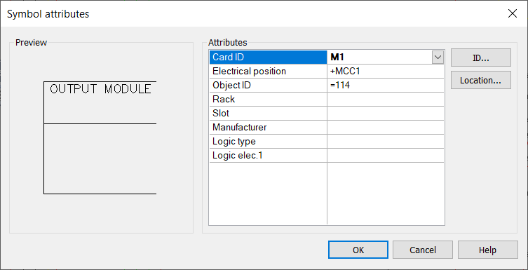
Enter attribute values to the column on the right. You can move between cells with the arrow keys. Device symbols ID and location can be selected with their respective buttons.
Inserting I/O symbols
Do the following:-
Select Schematics > Symbols > Logic schemas.
-
Select the desired symbol.
-
Indicate the insertion point in the drawing. The I/O symbol dialog opens.
-
In the ID field, enter a new ID, or use an ID from an existing card by clicking I/O Card. You can also retrieve the ID from an existing card by clicking I/O Card in the project tree.
-
Enter the channel number. If you selected an I/O card with channels already defined, you can select the channel from the drop-down menu.
-
If necessary, define the location information.
-
If you selected a card that has an address defined for the channel you selected, the address is filled in automatically.
-
The tag name identifies the I/O. Therefore, the same tag name cannot be used for different channels. If you want to create the I/O, this field is mandatory.
-
If you selected a card that has connector information defined, they are filled in automatically.
-
-
Click OK.
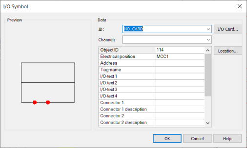
The location information is automatically filled in when you select an existing card.
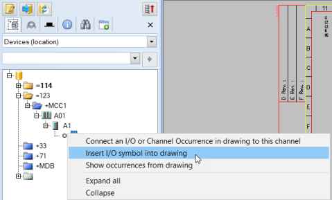
An I/O symbol can also be inserted from the project tree by selecting Insert I/O symbol into drawing: