Layout tab > Cabinets and feeders group > ![]() Management menu > Data network
Management menu > Data network
Data network incorporates building's generic data cabling that is used with local networks, telephone lines, security systems, etc.
With this function, you can create cabinets and their panels as well as connection points for the panels. The addresses for the connection points are generated automatically based on the cabinet, panel and port (CABINET.PANEL.PORT). The address is automatically updated if IDs are changed.
Do the following:
- Create product model for panels:
In the Product models tree, right-click an item and select Create new product model. The Product model dialog opens.
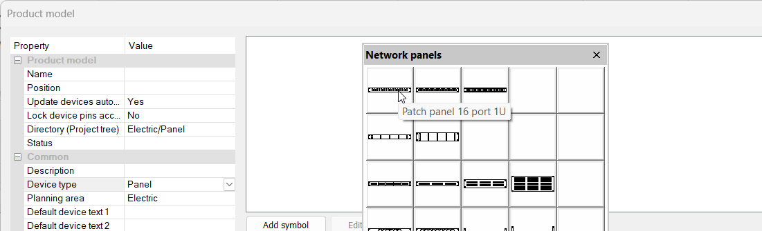
From the Device type drop-down menu, select Panel.
Add a symbol. When using official Electrical symbols, segments i.e. panel ports are created automatically.
 Show/hide example
Click Add symbol.
Select New Cabinet layout symbol.
Select Network panels.
Select the 16-port panel symbol.
For more information on product models, see Add and edit product models.
Click OK.
- Create product model for outlets:
In the Product models tree, right-click an item and select Create new product model. The Product model dialog opens.
Select a symbol for the outlet product model. You can use, for example, symbols from the ST 13.53, Communications and networking system menu. It is recommended to add Default cable item as additional information. That enables automatic cable creation later.
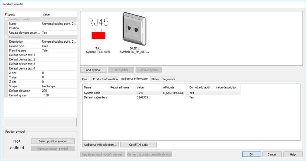 Segments i.e. ports of the outlet can be found from the Segments tab. When using Electrical symbols, these segments
will be created automatically. Port
type is usually used in data connections, Loop
in fire alarm systems.
Segments i.e. ports of the outlet can be found from the Segments tab. When using Electrical symbols, these segments
will be created automatically. Port
type is usually used in data connections, Loop
in fire alarm systems.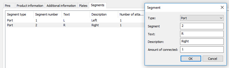
- Create cabinets:
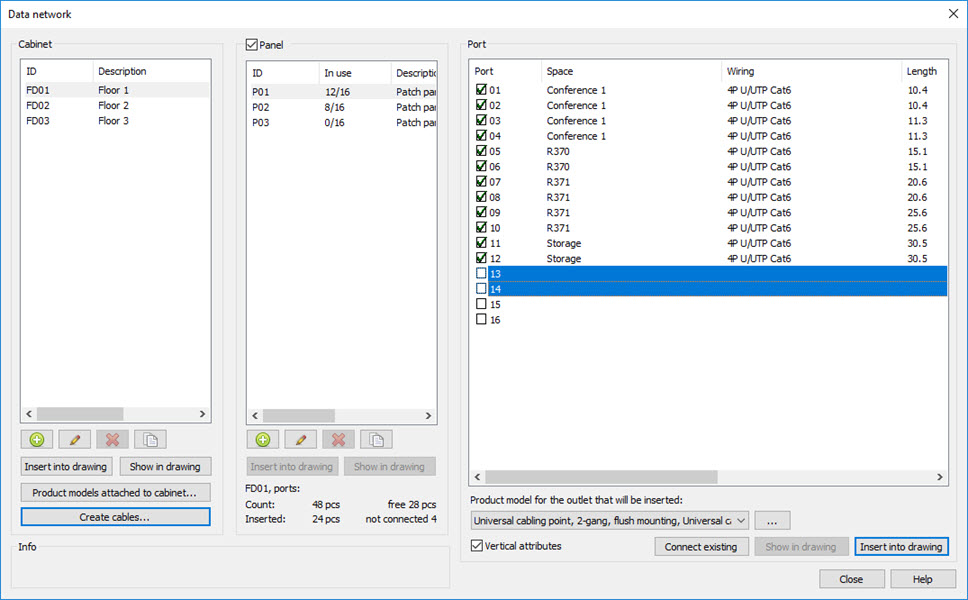
In the Data network dialog, click the
 button below the Cabinet list.
Enter the details.
- Attach product models to cabinets.
Select cabinet from the list.
Click Product models attached to cabinet. The Estimated product model amounts for network cabinet dialog opens.
Select product models and their estimated amounts for panels and outlets that will be used on the cabinet. Update and/or add descriptions for the selected set if necessary. You can use Template sets to load or save set of selected product models.
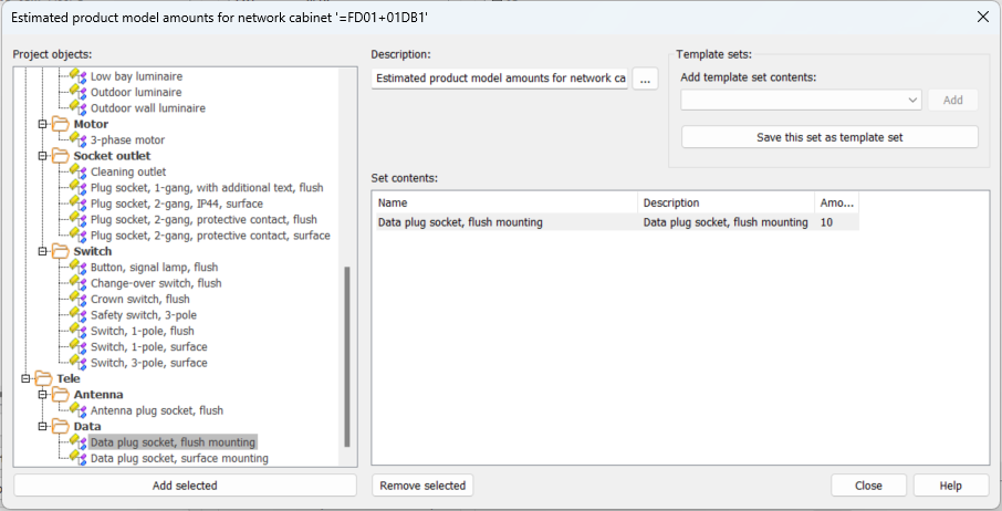
These product models will be listed when creating panels and outlets for the cabinet.
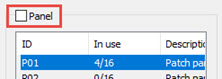
- Create panels:
Select the cabinet.
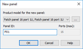
Click the
button below the Panel list. The New panel dialog opens.Select product model to use. The drop-down menu shows product models attached to the current cabinet but you can select any product model in the project by clicking the
 button.
 When using a product model the number of ports is automatically filled according to segments (ports) in the selected product model. Selection of product model is optional, if omitted, new device with given amount of ports will be created.
Enter panel ID.
- Click OK.
- Insert cabinets to the drawing: select the cabinet and click Insert into drawing. The type of inserted element depends on the type of the drawing: If drawing type is Layout , symbol selected for the cabinet will be inserted. If drawing type is Arrangement (not in scale), boundary will be inserted.
- Insert outlets to the drawing by selecting cabinet, panel and port. Product
model of outlet can be selected from the drop-down menu if they have been attached to the cabinet. With the
button any product model on project can be selected.
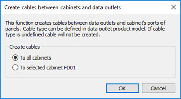
- Create cables. If the default cable item is defined to outlet's product model, cables between cabinet panels and outlets can be created automatically with Create cables. Cables can be created only to selected cabinet or to all cabinets. Cable will not be created if default cable item is not set for the product model.
- Connect existing outlet to panel. If outlets have been inserted without connecting them to a panel or outlets are previously inserted to drawing with another function, they can be attached by selecting cabinet, panel and ports to connect and pressing Connect existing. After that, select outlet from drawing.
Panels will not be inserted to layout drawings. Insertion is only enabled in Cabinet Layout drawings, where a symbol can be inserted with Insert into drawing.
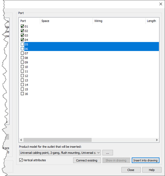
If a product model is selected, function reserves automatically the correct number of ports for the outlet according to product model. Ports can also be selected manually. If outlet has multiple ports, they can be selected by holding down the Ctrl key. To insert the outlet press Insert into drawing button. Insertion will continue until aborted by pressing Esc key or selected panel is full.
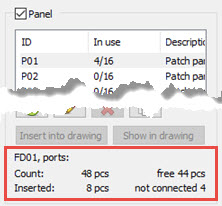
Outlets can also be inserted without assigning them to any panel by unchecking Panel checkbox. Outlets can be connected later with Connect existing.
The number of outlets inserted to drawing but not assigned to any panel is displayed below panels.
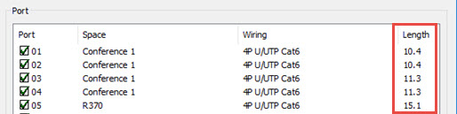
If cabinet and outlets are inserted to drawing, cable lengths between cabin and outlet will be calculated automatically.
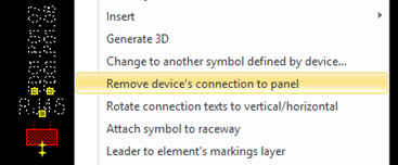
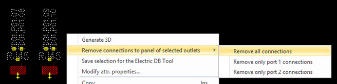
You can detach outlet from a panel by selecting from the outlets context menu (right mouse button). If there are multiple ports on selected outlets, select ports to disconnect from the list.
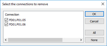
If multiple outlets are selected you can select which ports are disconnected.
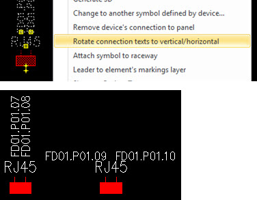
Ports connection text direction (horizontal/vertical) can be switched by selecting Rotate connection texts to vertical/horizontal from the outlet's context menu (right mouse button).