Layout tab > Devices group > ![]() Symbol functions menu > Scalable symbol
Symbol functions menu > Scalable symbol
With this function, you can create symbols for common electric devices with size information and insert them to drawings.
Do the following:
-
In the Saved properties section, select New.
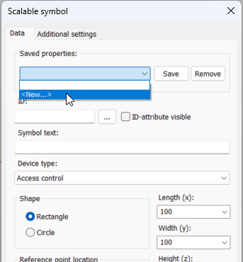
The New property set dialog opens.
-
Enter a name for the set, and click OK.
-
In the ID field, select an ID.
-
If you want ID attributes to be shown, select ID-attribute visible. Selecting this will automatically show the ID for lighting boxes, for example.
-
If necessary, enter the symbol text.
-
Select the device type.
-
Select the symbol shape.
-
Select the insertion point location.
-
Enter size data and elevation. You can indicate the elevation from the drawing by clicking the button next to the Elevation field.
-
Select the 3D symbol. There are three options of each 3D symbol: insertion point top, center or bottom.
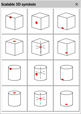
The 3D symbol is generated based on size data. 3D symbol and insertion points change if the shape or 2D symbol insertion point is changed.
-
Select the system to which the symbol is inserted.
-
If necessary, enter additional information:
-
Select the Additional settings tab.
-
Select the location and color of the symbol text.
-
Select whether a wipeout object is drawn for the symbol.
-
Select a marking symbol and its color which will be drawn inside the scalable symbol.
-
- Save the settings by clicking OK.
- Insert the symbol by indicating the insertion point.
When you modify the settings, you can save the changes with Save. You can remove your own symbol template by selecting it from the drop-down menu and clicking Remove.