|
|
Single-line tab > Cabinets and feeders group > Boundary |
| Schematics tab > Other functions group > |
|
| Cabinet Layout tab > Cabinets group > |
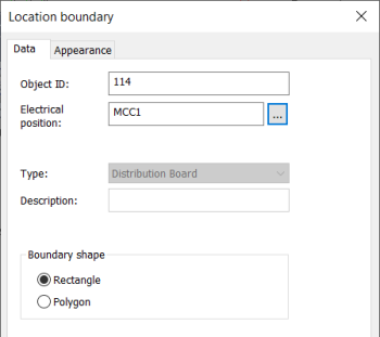
With this function, you can identify devices which belong to another location in the schema.
Do the following:
-
Enter Object ID, Electrical position, or both. The location boundary ID can be written in the drawing as a single ID (=123+CS1) or as two separate IDs (=123 and +CS1).
-
Select shape for the boundary.
-
If necessary, define the appearance:
- Select the Appearance tab.
- If necessary, select boundary color and line type. By default, the color and line type come from the settings file.
- If you want to add a background symbol for the boundary, select Show symbol and define the symbol or a raster image:
- If you want to add a symbol, do the following:
- Select the Symbol option.
- If necessary, select a new color from the drop-down menu.
- If you want to scale the symbol, select the scaling method from the Scaling drop-down menu.
- Click Select symbol or the preview pane.
- Select how you want to add the symbol:
- Select from drawing – Indicate the symbol in the drawing.
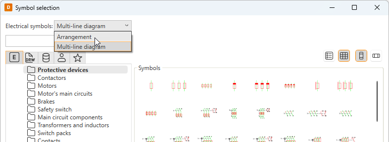
- Select from menu – Select the symbol in the Symbol selection dialog (see Symbol selection). By default, the symbols are shown based on the drawing type but you can select another drawing type (multi-line diagram or arrangement drawing) from the drop-down menu.
Click OK. The symbol you selected is now shown in the preview pane.
- If you want to add a raster image, do the following:
- Select Raster image. The Select symbol button changes to Select image.
- Click Select image and Select from disk.
- Select the desired image. The image will be scaled to fit the boundary while keeping the image aspect ratio unchanged. By default, raster images are saved to the Attachments sub-directory in the project directory.
- If you want to add a symbol, do the following:
- If you want to define a background fill color, select Boundary background color and then the desired color.
- Select whether to place the marking text inside or outside the boundary, and select the color.
- Click OK.
-
Click OK.
-
Draw the device boundary in the drawing.