Tips
General tips
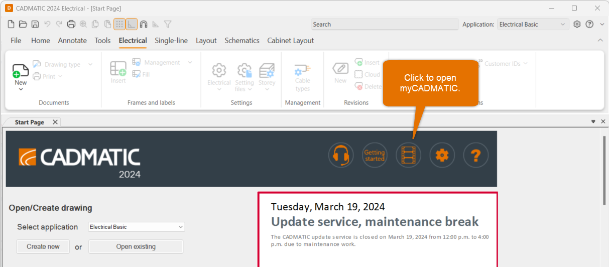
On the program start page at the top, you can find a video button. Click it, and register to myCADMATIC.
After your activation request has been approved, you get access to our video libraries at myCADMATIC.
Do the following:
-
Enter your name and email address, and click Sign up.
-
Check your email for the activation link.
-
Enter your desired password, and click Set password.
-
To have access to all content, click Submit activation request at the top of the page.
-
Enter your customer number and company name, and click Submit. We will send you a confirmation via email, and you can start exploring myCADMATIC.
You can easily edit various general settings for the user interface, automatic saving, grip, file format, reference drawings, etc. Select File > Settings > General settings.
To learn more, see General settings in the Online Help.
There are several shortcut keys you can use while working with CADMATIC Electrical. Try these, for example:
-
Ctrl pressed down – Enable/disable snap
-
Shift pressed down – Enable/disable ortho
-
F8 – Rotate symbol according to ortho angle
-
Tab – Change insertion point
-
Shift + right-click – Open a menu of other useful functions
To learn more, see Shortcut keys in the Online Help.
You can open a window called External references to the left side of the screen. You can easily add DWG, DXF, IFC, PDF and many image file formats as reference drawings to a document. After that, you can update, change, hide, lock, etc. reference drawings from there.
Note that you can define a conversion file for DXF and DWG files in File > Settings > General settings > Documents to define default colors for added reference drawings.
To learn more, see Manage reference drawings and Define document settings in the Online Help.
You can add new printers whenever necessary; select File > Settings > General settings > Print. In the Print style table section, you can define line widths for different colors and change the colors if needed.
To learn more, see Define print settings in the Online Help.
Layout tips
When you start a new drawing, Layout will ask about the printing scale (which indeed only affects printing). It is recommended to set the symbol scale factor according to the scale. You can edit these later by selecting Home tab > Modify group > Scale menu.
To learn more, see Scale objects in the Online Help.
The Drawing sheet function on the Layout tab, in the Frames and sheets group allows you to create a layout, print frame and viewport at one go. You can easily define automatic scales for the desired paper sizes, and define marginals and insertion point. Later, you can edit the settings by selecting Edit drawing area from the Drawing sheet menu.
To learn more, see Set and edit drawing area in the Online Help.
For listing functions, select Layout tab > Other functions group > List functions.
To learn more, see List functions in the Online Help.
To open the Wiring window to the left of the screen, select Layout tab > Wiring group > Draw. Then define the wiring style. After indicating the first point, check the useful shortcuts listed to the command line for additional settings for angles, curving settings, etc.
To learn more, see Draw wiring in the Online Help.
Positioning functions are available
To learn more, see Positions in the Online Help.
With the File > Print > Print frames from drawings function, you can select which documents you want to print. Note that you can construct the file names from the printing function with the label values. Otherwise, they will be automatically generated.
To learn more, see Print frames from drawings in the Online Help.
You can draw cableways with the Layout tab > Cableways group > Draw function. Edit cableways dimensions and style – you can even change the settings while drawing. You can also edit these objects later by clicking them. If you need to edit the whole cableway system, such as the width, you can click a cableway part and then press Ctrl + Shift + A to get all cableway parts to grip at once before editing the width.
To learn more, see Draw cableways and Edit cableways and vertical cableways in the Online Help.
You can create collision geometry by selecting Layout tab > 3D and view group > 3D functions menu > Collision checking menu > Create collision geometry. After that, you can create collision arrows by selecting Collision checking of 3D parts from the Collision checking menu. You can check collisions between Electrical elements and IFC reference drawing elements, such as HVAC and building elements.
To learn more, see Check for collisions in the Online Help.
Select Layout tab > 3D and view group > 3D. The function generates 3Ds, changes to top-side view and turns shading on. Now you can also rotate the view by placing your mouse pointer to a suitable focus point and pressing Ctrl continuously while moving the mouse. The view then rotates around the selected focus point.
You can create a list of all electrical symbols by selecting Layout tab > Other functions group > List functions menu > Electrical symbol list.
You can open the Electrical and Electrical 2 windows with project tree to the left side of the screen. You can select the kind of objects you want to view from the drop-down menu.
You can use the tree to see all objects in the current drawing: Find the desired object (such as a device or a cable), and right-click it to open a menu with available functions. Select Show occurrences from drawing. If the object has multiple occurrences, you can move to the next occurrence with Enter. Finally, close the function with Esc.
Schematics tips
When you insert devices inside boundaries, they will inherit the data from them. For example, if you draw +MCC1 location boundaries, devices inserted inside the boundaries get it automatically.
The different boundary functions in the Schematics tab > Other functions group > Boundaries menu are Location boundary, Device boundary and Circuit boundary.
After selecting one of these functions, you can define the appearance of boundaries on the Appearance tab.
To learn more, see Draw location boundaries, Draw device boundaries and Draw circuit boundaries in the Online Help.
When you draw wiring or a cable without connecting it to a device or a bounded area, you can create a reference. You can continue wiring on another sheet, or insert an unpaired reference and connect it later. From the wire’s/cable’s right-click menu, you can insert a reference later. If you move the wires or change sheets, the references update automatically.
To learn more, see Markings in the Online Help.
Contactors, coils, contacts and auxiliary contacts, for example, automatically generate references to each other when they have the same ID and are occurrences of each other. References also update automatically.
First you need to draw undefined wires or busbar wires, and then select the Schematics tab > Markings group > Cable menu > Connect and mark cables and its wires function. Draw a line through all the desired wires belonging to the same cable (follow the command line instructions). After this, you can define cable data to create smart wiring markings and cable marking automatically.
To learn more, see Connect and mark cable and its wires in the Online Help.