Schematics tab > Devices group > ![]() Connectors menu > Terminal strip
Connectors menu > Terminal strip
With this function, you can add new terminal strips, edit existing terminal strips and add terminal strips into a drawing.
The dialog shows a location based tree for terminal strips. The terminal blocks for the selected terminal strip are displayed in the list on the right. The color of a terminal block indicates the current status:
- Yellow icon – Not connected
- Green icon – Connected
- Blue background – Product model's device
Creating terminal strips
Do the following:
-
Select to draw the terminal strip either horizontally or vertically.
-
Select the root node or the desired location.
-
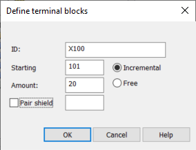
Click New. The Define terminal blocks dialog opens.
-
Enter a unique ID for the terminal strip.
-
Enter the first number.
-
If you select Incremental, block numbers are automatically incremented from the starting number until the total number of blocks defined in the Amount field is reached.
-
If you select Free, numbers are asked separately for each block.
-
-
Enter the number of terminal blocks to generate.
-
If you want to add an extra pair shield block for each pair of terminal blocks, define the number/ID of the pair shield.
-
Click OK. The terminal strip has now been created.
You can remove a terminal strip by selecting it and clicking Remove.
Adding terminal blocks for a terminal strip
Do the following:
- Select the terminal strip to which you want to add terminal blocks.
-
Click Add. The Define terminal blocks dialog opens.
-
Enter the first number.
-
If you select Incremental, block numbers are automatically incremented from the starting number until the total number of blocks defined in the Amount field is reached.
-
If you select Free, numbers are asked separately for each block.
-
-
Enter the number of terminal blocks to generate.
-
If you want to add an extra pair shield block for each pair of terminal blocks, define the number/ID of the pair shield.
-
Click OK. The terminal blocks have now been added.
You can remove terminal blocks by selecting the desired terminal strip and then the terminal blocks and clicking Remove.
Editing terminal strip ID or terminal block numbering
You can edit the selected terminal strip ID and/or the selected terminal strip block numbers.
Do the following:
- Select the terminal strip and then the terminal blocks to edit.
-
Click Edit. The Edit terminal strip dialog opens.
-
Edit the terminal strip ID if necessary.
-
If you want to edit the numbering, do the following:
-
Select Change numbering.
-
In the Starting field, define where to start the renumbering.
-
Select whether to use incremental numbering or free numbering where numbers are asked separately for each terminal block.
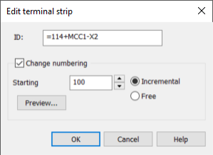
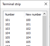
With Preview, you can check the numbering changes before making the actual changes.
-
-
Click OK.
Drawing terminal strips
Do the following:
-
Select the terminal strip you want to draw.
- If you want to add extra blocks to fill in the gaps in terminal block numbering, select Fill gaps in terminal block numbering.
- If you want to insert an ID symbol to the end of the terminal strip, select Insert ID-symbol into drawing.
- If you want to draw terminal blocks with wider module spacing that is suitable for the main circuit, select Main circuit.
- Select whether to draw internal and/or external wiring references.
- Insert the selected terminal strip into the drawing by clicking Draw.