|
|
Spaces tab > Edit group > Space's general data |
CADMATIC Electrical
-
Hatch pattern: S_TILAKUVIO
-
Background color: S_TILATAYTTO
-
Boundaries of space: S_TILARAJAUS
-
Number of space: S_TILANUMEROT
-
Name of space: S_TILANIMITYKSET
-
Area of space: S_TILAALAT
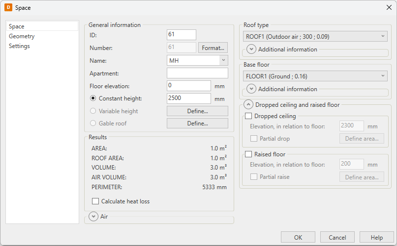
With this function, you can edit the general data of the selected space object.
Do the following:
-
Enter the general space object data:
-
ID – The ID of the space is an individual integer for each space. The ID cannot include any other characters than numbers.
-
Number – The number is an identifier which is shown in the drawing. Click Format to define the number format.
 Show/hide details
In the Space number, format dialog, define the following:
-
Space number = ID number – The space's number is the ID number. You cannot add any other characters to the number.
-
Formatted space number including ID number – Define a format of the number. Enter [ID] to include the ID in the space number.
-
Space number as a free text – Define a number of your choosing for the space object.
Keep in mind that entering the number as a free text excludes the space from certain automatic functions, such as renumbering the spaces when copying them. You have to correct the number by hand every time.
-
-
Name – Space names are recorded in the file HUONETUN.TXT. You can add your own space identifiers by opening the file in a text editor (e.g. Windows Notepad editor), if needed.
-
Apartment
-
Floor elevation
-
-
Select the determination type of the space height. A space can have a constant height or it can be defined by a three-dimensional plane in any direction. Thus, the roof can be defined by only two plane that cuts through the space. If the space is a combination of heights and has both a straight and an angled roof, you have to define it in two sections.
-
Constant height – Enter the space height in millimeters.
-
Variable height – You have to have three-point height data of the room. Based on these points, the program determines a plane that forms a "ceiling" for the room.
Show/hide procedure
Do the following:
-
Click Define.
-
Select the first known point.
-
Enter the point's elevation.
-
For all three points, select the point and enter the elevation.
-
-
Gable roof – You have to have four-point height data of the room. Based on these points, the program determines planes that form a "ceiling" for the rooms.
Show/hide procedure
Do the following:
-
Click Define
-
Select the first known point.
-
Enter the point's elevation.
-
Repeat steps b and c for all four points.
-
-
-
Select the roof structure.
-
If the type of the roof is Intermediate floor, select whether different temperature is used in the space above it. If yes, enter the temperature.
-
Enter the surface material or finishing of the roof.
-
For Area differs from space area, select whether the real roof area is different from the defined roof area, such as an inclined roof. If yes, enter the area of the roof.
-
If the space has skylights, select Skylights. Then enter the total area of the skylights into the field, and select the skylight type from the drop-down menu.
-
Select the structure of the base floor.
-
If the type of the base floor is Intermediate floor, select whether different temperature is used in the space below. If yes, enter the temperature.
-
Enter the surface material or finishing for the base floor.
-
For Area differs from space area, select whether the base floor area is different from the defined space area. If yes, enter the area of the base floor.
-
If necessary, calculate heat loss for the space.
Show/hide procedure
Do the following:
-
In the Results section, select Calculate heat loss.
-
Enter the inside temperature of the space.
-
Enter the supply air temperature. If the space has forced-air heating, the room temperature defines the incoming air temperature.
-
Enter the summed power of the additional heaters.
-
If air leakage needs to be taken into account in the calculations, select Leakage air and then the applicable air leakage coefficient.
-
Select whether thermal bridges are taken into account in the calculations.
If yes, define the conductance:
-
Click the
 button.
 -
Select the material(s).
-
Enter the conductance.
-
Click OK.
-
Repeat the steps for each of the thermal bridges.
-
-
-
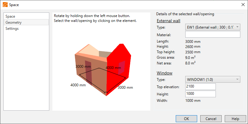
Edit the walls and openings of the space on the Geometry tab.
Show/hide procedure
Do the following:
-
Select the Geometry tab from the left.
-
Select a wall from the picture. The information of the selected wall is displayed on the right.
-
Edit the size or height of the window, for example.
-
-
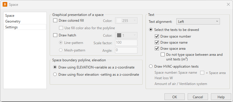
Define the style of the space on the Settings tab.
Show/hide procedure
Do the following:
-
Select the Settings tab from the left.
-
Select whether a background fill is drawn into the space. If yes, select a fill color from the drop-down menu.
Select whether the space boundary polyline is drawn with the fill color.
-
If you want to draw a background hatch pattern into the space, do the following:
-
Select Draw hatch.
-
Select a color from the drop-down menu.
-
Select the background pattern type (line pattern or mesh pattern).
-
Enter the pattern size factor, which is the distance between the drawn lines.
-
Enter the hatch pattern angle.
-
-
Select a text format for the space:
-
Select the text alignment method.
-
Select whether the space number, name, or area are drawn. If yes, select whether the space between the area and the unit is left out or not.
-
Draw HVAC-application texts – When using HVAC application presentation, the space data is logged in the following form:
Space name: Space number
Heat loss W
Air flow rate inlet / Ventilation networks
Air flow rate outlet / Ventilation networks
You cannot modify the information.
-
-
-
Click OK.