Define and insert objects created in the database
Do the following:
-
Create a new sheet in the E-0-Schematics-01-501.drw drawing by going, for example, to the second sheet and pressing Ctrl + PgUp.
-
Define a location to the frame:
-
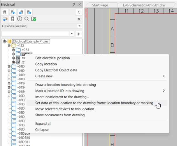
In the Electrical window, select Devices (location) from the uppermost drop-down menu.
-
In the project tree, right-click +MCC1 and select Set data of this location to the drawing frame, location boundary or marking.
-
Select the drawing frame, and press Enter. The frame’s location information is automatically updated to =123+MCC1.
-
-
Insert a location boundary to the drawing:
-
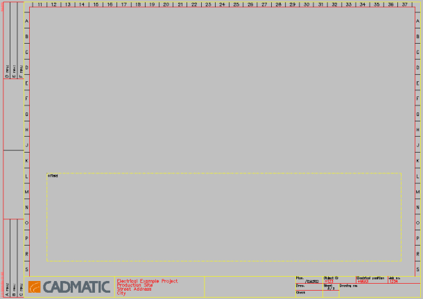
In the project tree, right-click +Field and select Draw a location boundary into drawing.
-
Draw a large boundary to the bottom part of the drawing.
-
-
Insert terminal blocks to the drawing:
-
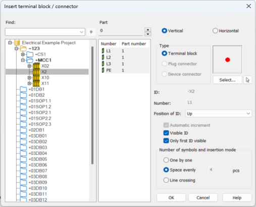
In the Devices (location) project tree, search for the X2 terminal strip either below location =123+MCC1 or with the search function.
-
Right-click it, and select Insert terminal blocks of this strip in drawing.
-
Define the settings as follows:
-
Select the desired pins from the middle section with Shift or Ctrl.
-
Select Vertical.
-
Type – Terminal block
-
Position of ID – Up
-
Select Visible ID.
-
Select Only first ID visible.
-
Number of symbols and insertion mode – Space evenly, 4
-
-
Click OK.
-
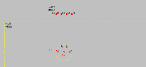
Insert the terminal blocks to the drawing above the location boundary. Leave the distance between terminal blocks as 7 (raster jump with 3.5 x 2).
-
-
Insert a device:
-
In the project tree, search for the device M1 below +Field.
-
Right-click, and select Insert an occurrence of this device into drawing. The Insert symbol dialog opens. The device does not have a symbol yet.
-
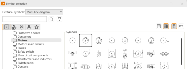
Click Other symbol. The Symbol selection dialog opens.
-
Select Motors and then the 3-phase motor:
-
Click OK.
-
Insert the motor symbol inside the +Field location boundary, right below the terminal blocks so that the terminal blocks and motor terminals align.
The Symbol attributes dialog opens.
-
Click OK.
-
-
Draw a busbar between the terminal strip and the motor:
-
Select Schematics tab > Wiring group > Draw busbars.
-
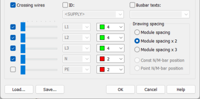
Define the settings as follows:
-
Click OK.
-
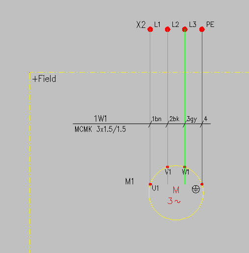
Draw the busbar by selecting L1 terminal as the first point, and go down to connect to motor M1 as the second point.
-
Delete excess wires below L2 and L3.
-
-
Define the cable and its wires in the drawing:
-
In the Electrical window, select Wirings from the uppermost drop-down menu.
-
Find 1W1, right-click it and select Connect and mark cable and its wires.
-
Select the first point to be to the right of the busbar, then draw the line across to the left side.
-
Accept the wire connections in the connection dialog.

Note: Wire connections are done automatically. If there are terminal blocks with pin number PE or N, they are automatically connected to the PE and N wires. Wire connections can be changed in this dialog if the suggestions are not desirable.
-