Manage raster images
With the raster image functions, you can combine raster images with CAD objects in CAD drawings. You can, for example, have a scanned raster image of a floor plan in a drawing and then design an electrical design on top of it. The images are always converted to black and white format.
Raster images are for example files that are scanned from paper drawing. Raster image consists of pixels and differs very much from vector drawings (i.e. CAD drawings).
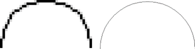
On the left is a raster image and on the right is a vector drawing (arc).
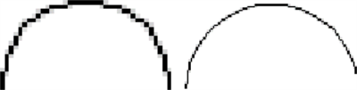
Scanning resolution defines how many pixels are used to represent the original drawing. In the picture below the image on the right has been scanned using higher resolution.
Multiple raster images can be attached to one CAD Drawing. All attached raster images are saved in file FILE_NAME.RIF where FILE_NAME is the name of the CAD Drawing. All modifications affect to only one raster image at a time (active raster image).
Raster images are saved into RIF file. RIF file is named after the CAD Drawing and it includes all loaded raster images. The same name of the CAD Drawing (.drw) and the RIF file is the only link between CAD Drawing and the raster images. If this link is ok Rasta application loads the images in RIF file automatically when opening the drawing.
After raster images have been saved to RIF file the original scanned image files are no longer needed.
The most common Windows image file formats are supported.
Drawings including raster images should be printed using printer drivers that print the data in raster mode. If the printer driver uses vector based data the printing process is slow.