
|
Single-line tab > Markings group > Object info |
|
|
Layout tab > Markings group > Object info |
|
|
Schematics tab > Markings group > Object info |
You can also start this function by right-clicking an object and selecting Add object information.
With this function, you can add information or a marking symbol to the drawing.
-
When you start the function via the ribbon, you can select several objects for which to add the information.
-
When you start the function by right-clicking, you can select one object only.
Learn more:
Add object information definitions
Do the following:
-
Start the function in one of the following ways:
-
On the ribbon, select the Markings group > Object info. Then indicate a device occurrence or wiring reference from the drawing. When you start the function via the ribbon, you can later select several objects for which to add the information.
-
Select the desired object, right-click and select Add object information. When you start the function by right-clicking, you can select one object only.
The Add object information dialog opens. The information available is grouped in the tree view on the left.
-
-
Add information to the list on the right by double-clicking in the project tree. You can define the order of attributes by clicking the arrow buttons.
-
Select the attribute for which you want to define the settings.
-
Define what you want the selected attribute to look like:
-
Add a prefix and/or a suffix for the selected attribute by entering the text to the empty fields before and after the actual information.
-
Define the style, size, color, and width. By clicking the
 button next to Style, you can edit the text styles.
-
-
Define the settings for the marking:
-
You can define the desired alignment for the text.
-
You can easily use the same offset value in different drawings with the Use previous offset value for inserting setting. When selecting this option, you do not need to insert the symbol. Instead, it is automatically inserted according to the saved offset.
If the previous value has not been saved yet, the option is disabled. The offset value is saved after inserting the symbol, and it will then be available the next time.
-
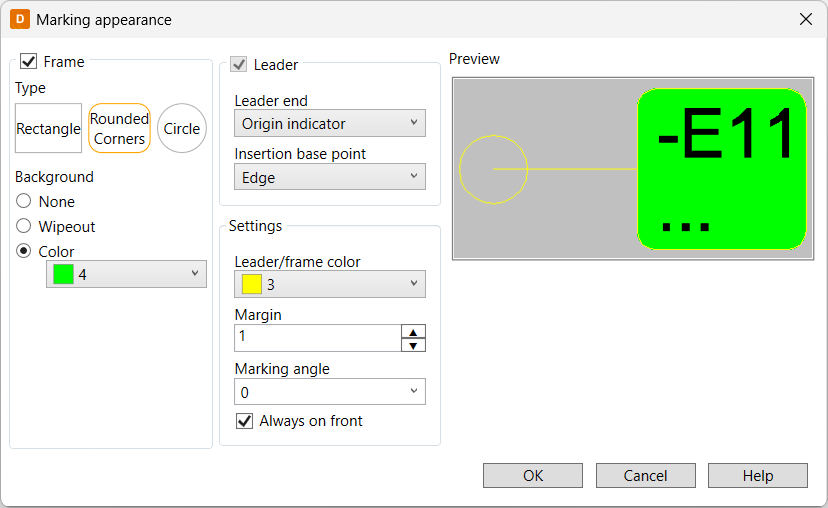
Select to include a frame and/or a leader. You can define their appearance (such as colors) by clicking Appearance.
 Show/hide details
In the Marking appearance dialog, Frame and Leader are selected if you selected them in the Add object information dialog. However, you can also select and clear selections in this dialog.
The frame adjusts automatically according to the length of the attribute values.
The Preview section shows how your selections affect the marking.
-
-
Define settings for each attribute in the same way.
-
If you want to save the settings for later use, do the following:
-
In the upper part of the dialog, click the
 (Add attribute set) button. The Save attribute set dialog opens.
 -
In the Set name field, enter a descriptive name for the settings and click OK.
By selecting a saved set from the Selected drop-down menu, you can view, edit and use the settings.
-
-
Click OK.
-
Depending on how you started the function as well as your previous selections, do as follows:
-
If you started the function via the ribbon:
-
If you selected to use the previous offset value, you do not need to insert the symbol. Instead, select all the objects you want to add the information for.
-
If you selected to include a leader, indicate the end point for it. Then select all the objects you want to add the information for and indicate the leader end points.
-
If you did not select to use the previous offset value or include a leader, indicate the symbol insertion point. Then select other object for which to add the information and indicate the symbol insertion points.
When inserting, you can rotate the symbol with F8 to set the desired angle. The angle stays when updating, moving, or copying the symbol.
-
-
If you started the function via the context menu and selected to include a leader, indicate the end point for it.
-
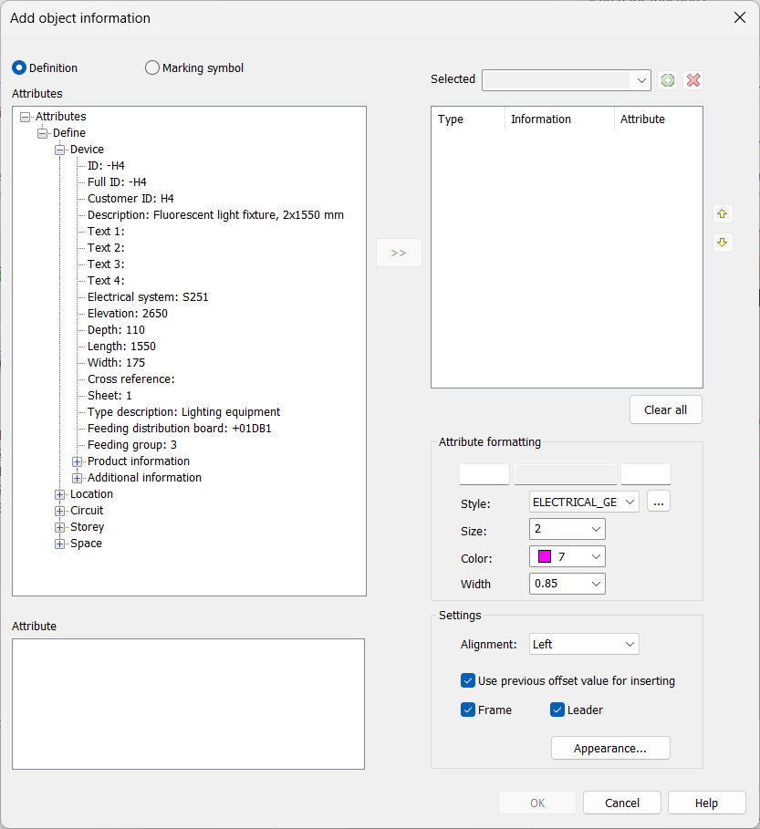
If you selected a cable belonging to a group, group information is shown below Group.
You can also add product information to the drawing, even when product information has not been assigned to the device.
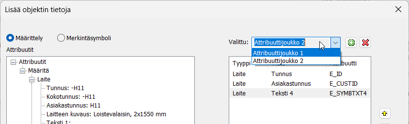
If necessary, you can edit symbols added with the Add object information function: Right-click the object information symbol, and select Edit symbol. The Add object information dialog opens, allowing you to make changes.
Add marking symbols
Do the following:
-
Start the function in one of the following ways:
-
On the ribbon, select the Markings group > Object info. Then indicate the desired device occurrence or wiring reference from the drawing.
-
Select the desired object, right-click and select Add object information.
The Add object information dialog opens.
-
-
Select Marking symbol.
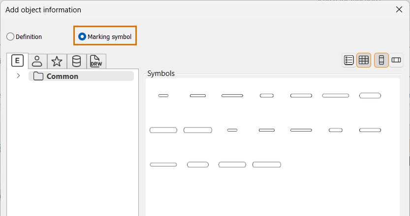
On the left of the dialog, you can select the desired tab to filter the symbols you want to view as follows:

Electrical symbols – This tab shows you all the Electrical symbols available.

User's symbols – This tab shows you the symbols you have saved with the Save user symbol function or imported from the user icon menus.

Favorite symbols – This tab shows you the symbols you have defined as your favorites.

Symbols in current project – This tab shows you all the symbols in the project.

Symbols in current drawing – This tab shows you the symbols that have been inserted in the active drawing.
Show/hide details
The tree structure language is based on what has been selected from the Language of symbol dialogs and info box header drop-down menu in Electrical settings.
Symbols are shown according to your selection in the Symbols section. When you hover over a symbol, the symbol description is shown. The symbol description language is based on what has been selected from the Language of symbol dialogs and info box header drop-down menu in Electrical settings.
The name and description (according to the Electrical setting) of the selected symbol is shown below the Symbols section.
-
If you want to include a leader, select Leader.
-
If you have inserted a symbol before and want to use the same offset, select Use previous offset.
-
Double-click the desired symbol.
-
Depending on your selection:
-
If you did not select to include a leader, indicate the symbol insertion point, enter symbol attributes, and click OK.
-
If you selected to include a leader, indicate the leader start and end points.
-