Insert symbols

|
Schematics tab > Devices group > Symbols |
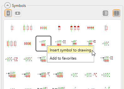
In the Symbols window, you can insert a symbol into the drawing via any of the tabs by double-clicking the symbol and indicating the insertion point. Alternatively, you can right-click the symbol and select Insert symbol to drawing:
When you select to insert a terminal block, plug connector, or device connector symbol, the insert dialog opens.
When you select to insert a marking symbol, you need to indicate the main symbol; it is not possible to insert a marking symbol on its own.
Tip: When inserting a symbol on a wire line, the function cuts the lines under the symbol. You can therefore insert a symbol on top of existing wiring.
Tip: When you insert a symbol on top of a horizontally drawn wire line, the function also turns the symbols and included attributes horizontally. Attributes are also inserted more sensibly.
In the Symbols window, in the Symbols section, you can create product models based on the symbols by right-clicking the selected symbol and selecting Create new product model:
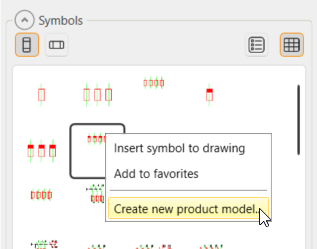
The New product model dialog opens, and you can define the information as for any other product model. The new product model will get the 2D and 3D symbols and the device type from the selected symbol.