Schematics tab > Other functions group >  Boundaries menu > Circuit boundary
With this function, you can distinguish devices which belong to another circuit in the schema.
Do the following:
-
Enter the circuit code, number and description, if necessary.
-
Select the shape for the boundary.
-
If necessary, define the appearance:
- Select the Appearance tab.
- If necessary, select boundary color and line type. By default, the color and line type come from the settings file.
- If you want to add a background symbol for the boundary, select Show symbol and define the symbol or a raster image:
- If you want to add a symbol, do the following:
- Select the Symbol option.
- If necessary, select a new color from the drop-down menu.
- If you want to scale the symbol, select the scaling method from the Scaling drop-down menu.
- Click Select symbol or the preview pane.
- Select how you want to add the symbol:
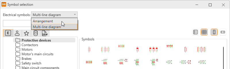
- From menu – Select the symbol in the Symbol selection dialog (see Symbol selection). By default, the symbols are shown based on the drawing type but you can select another drawing type (multi-line diagram or arrangement drawing) from the drop-down menu.
- From drawing – Indicate the symbol in the drawing.
Click OK. The symbol you selected is now shown in the preview pane.
- If you want to add a raster image, do the following:
- Select Raster image. The Select symbol button changes to Select image.
- Click Select image and Select from disk.
- Select the desired image. The image will be scaled to fit the boundary while keeping the image aspect ratio unchanged. By default, raster images are saved to the Attachments sub-directory in the project directory.
- If you want to add a symbol, do the following:
- If you want to define a background fill color, select Boundary background color and then the desired color.
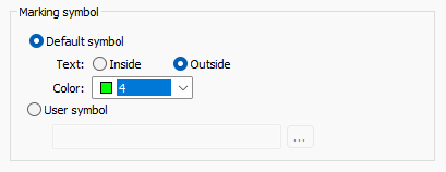
- Define whether to use the default marking symbol or your own symbol.
- If you want to use the default symbol, select Default symbol and then select whether to place the marking text inside or outside the boundary. You can also select the desired color.
- If you want to use your own symbol, select User symbol and then click the
 button to select the symbol from a menu, from the drawing, or from a file.
From menu – Select the desired symbol in the Symbol selection dialog.
 Show/hide procedure
Do the following:
Select the desired tab:

Electrical symbols – This tab shows you all the Electrical symbols available.

User's symbols – This tab shows you the symbols you have saved with the Save user symbol function or imported from the user icon menus.

Favorite symbols – This tab shows you the symbols you have defined as your favorites.

Symbols in current project – This tab shows you all the symbols in the project.

Symbols in current drawing – This tab shows you the symbols that have been inserted in the active drawing.
Double-click the symbols you want to select. Alternatively, right-click them and select Add. The symbols are moved to the selected symbols.
Click OK.
For more information on the Symbol selection dialog, see Symbol selection.
You can also filter the symbols more by opening and selecting the tree nodes. In the Symbols section, symbols are shown according to your selection.
From drawing – Select the desired symbol in the drawing.
File – Select the document type, and then the symbol.
Sub type 2 of the marking symbol needs to be Circuit boundary, Device boundary, or Location boundary according to the boundary about to be drawn.
- Click OK.
-
Click OK.
-
Draw the boundary in the drawing.
By right-clicking a boundary and selecting Boundary properties, you can edit and update boundary settings.