|
|
Single-line tab > Cabinets and feeders group > Boundary |
| Schematics tab > Other functions group > |
|
| Cabinet Layout tab > Cabinets group > |
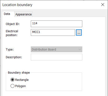
With this function, you can identify devices which belong to another location in the schema.
Do the following:
-
Enter Object ID, Electrical position, or both. The location boundary ID can be written in the drawing as a single ID (=123+CS1) or as two separate IDs (=123 and +CS1).
-
Select shape for the boundary.
-
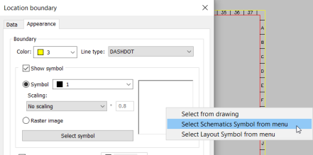
On the Appearance tab, adjust boundary appearance.
-
Select boundary color and line type.
-
If you select Show symbol, you can add a raster image or symbol inside the boundary.
-
You can define the color and scaling method for the symbol. In addition to selecting a symbol from the drawing, you can select a Schematics or Layout symbol from the menu. To see the options, either click Select symbol or the symbol pane:
-
Select a raster image by clicking Select image and then selecting Select from disc. The image will be scaled to fit the boundary while keeping the image aspect ratio unchanged. By default, raster images are saved to the Attachments sub-directory in the project directory.
-
-
You can define the boundary background color by selecting Boundary background color.
-
You can locate the marking text either inside or outside the boundary. You can also define the color for the text.
-
-
Click OK.
-
Draw the device boundary in the drawing.