| Schematics tab > Wiring group > |
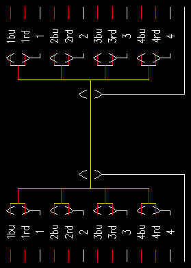
With this function, you can draw cable termination.
You can decide whether you want to connect cable termination to terminal blocks or not. If cable termination is drawn to a terminal block, the wires will be connected automatically.
Note: Project's Visibility of Type in drawing as well as the Module spacing setting affect the drawing of cables.
The program remembers the settings you previously defined in the Cable termination dialog.
Do the following:
-
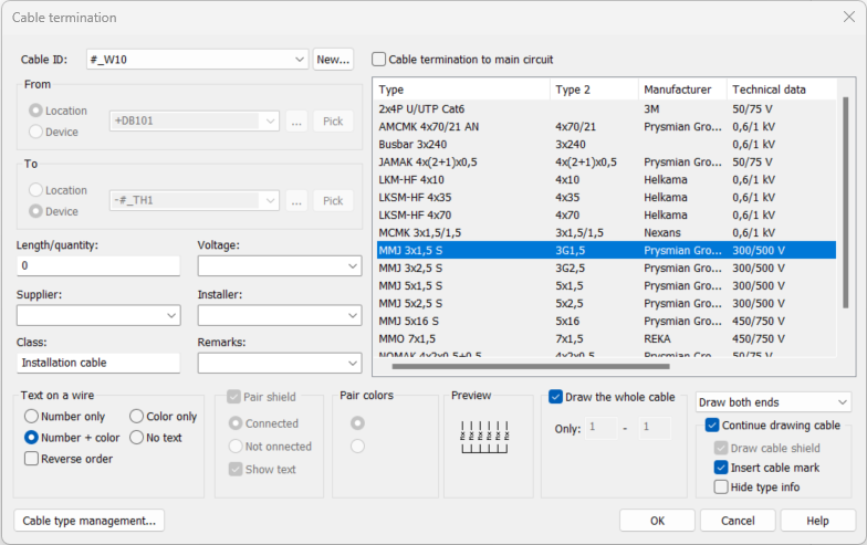
Create a new cable by clicking New and entering the cable ID, or select an existing cable from the drop-down menu. If the cable already exists, its information will be loaded to the dialog.
-
Enter the From and To information. You can also select them from the drop-down menu, from the location tree with the
 button or from the drawing with Pick.
 - If you do not want to use the default grid spacing, select Cable termination to main circuit. By default, the grid spacing will be as defined in the Module spacing setting (3.5 mm or 2.5 mm). If you select the Cable termination to main circuit option, the grid spacing will be either 2 x 3.5 mm (= 7 mm) or 2 x 2.5 mm (= 5 mm), according to the Module spacing setting.
-
Select the cable. Fill in the additional information, such as length, voltage, supplier, etc., if necessary.
- Select additional drawing
settings:
Select text markings for the wires.
Select drawing of a pair shield. With Show text, you can either show or hide the pair shield text.
Select the color order of the wires.
Select if the cable is drawn entirely (Draw the whole cable)or just part of it (e.g. only pairs 1–4).
Select other details: whether to draw cable termination to both ends of the cable, to continue with drawing a cable, to draw a cable shield, to insert cable mark, or to hide type info.
Hide type info is enabled when the project's cable marking settingVisibility of Type in drawing has been set to According to visibility setting of symbol's attribute. If the setting has been set to Always visible or Not visible, hiding is disabled.
-
Begin drawing by clicking OK.
-
Insert the starting point of the cable termination.
-
If you selected Continue drawing cable, draw cable from the termination.
-
If you selected Draw both ends, insert endpoint of the cable termination.
-
If you selected Insert cable mark, select and insert cable marking.


In database projects, you can connect a wire from cable termination to the From/To pins in the drawing by right-clicking and selecting Connect wire. The function is available when the wire has no occurrences in any drawings. If necessary, you can remove the connection with the Clear wire's connection function.