|
|
Layout tab > Other functions group > Auxiliary functions menu |
This menu contains auxiliary functions, which are used rarely. These functions are usually common to all applications.
With the following functions, you can load the symbol definition from the disc to the drawing:
-
Load all symbols from disc – Retrieve all symbol definitions to the drawing. The function will only load symbol graphics, not attributes. Attributes stay in the same location after loading.
-
Load symbols from disc and replace them in drawing – Retrieve all symbol definitions to the drawing, remove old symbol definitions and change new symbol definitions to the drawing. Possible new attributes will appear. Attribute locations will according to symbol definition.
-
Load selected symbol from disc and replace them in drawing – Retrieves all symbol definitions to drawing, removes old symbol definitions and changes new symbol definitions to drawing. Possible new attributes will appear. Attribute locations will according to symbol definition.
Functions can be used when a symbol has been retrieved to the drawing, the symbol has been exploded and changed, and the new version has been saved in the disc but not in the drawing. The old version of the symbol is still in the drawing. When retrieving the symbol, the program always retrieves primarily the symbol definition from the drawing and thus selects the old version of the symbol.
Define attribute mappings for symbols to use in Change Symbol function
With this function, you can find out the symbol type.
Do the following:
-
Select a function.
-
Select a symbol. The function shows the symbol type:

If the symbol type needs to be changed, do it with the Define symbol types to symbols in symbol directory function.

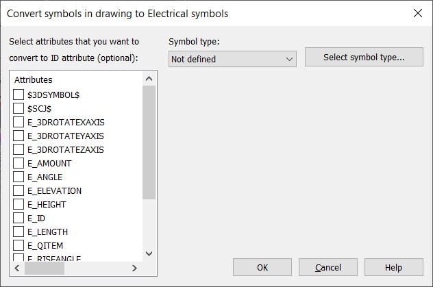
With this function, you can convert symbols with symbol type Not defined to Electrical symbols. These symbols can be originated from other applications, for example.
Conversion enables devices to be created from the foreign symbols. Furthermore, you can then use the symbols with other Electrical functions. The conversion adds symbol type and ID attributes for the selected symbols. If a symbol already has another attribute for ID, this can be converted to the Electrical ID attribute (E_ID). Otherwise, a new ID attribute will be added.
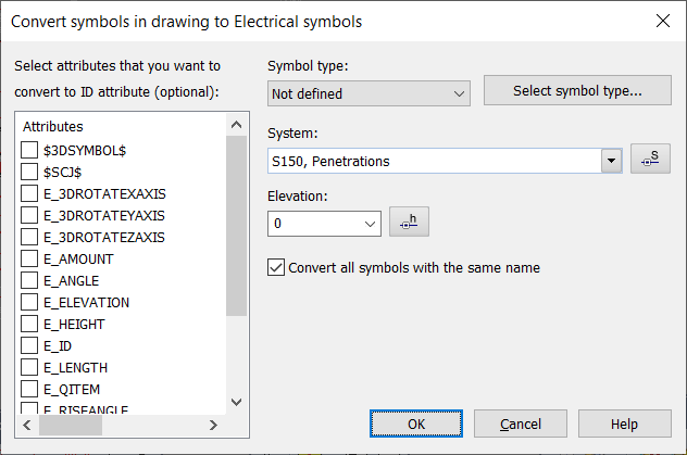
In Layout, you can also define system (mandatory) and elevation for the symbols you are converting, and create IDs for all symbols with the same name.
Do the following:
- Select symbols to convert. You can select multiple different symbols which will then get the same symbol type. The Convert symbols in drawing to Electrical symbols dialog opens.
- Select attributes that hold device IDs, if there are any. If you do not select anything, a new ID attribute will be created.
- Select the (main) symbol type from the drop-down menu. You can also define more accurate sub types by clicking Select symbol type.
- If you opened the dialog from Layout, also define the following:
- Select the desired system from the drop-down menu, or click the
 button and pick it from the drawing.
 - In the Elevation field, enter the desired elevation or click the button and pick it from the drawing.
- If you want to create IDs for all the symbols with the same name, select Convert all symbols with the same name. Otherwise, only the symbol type will be changed for the symbols not selected.
- Select the desired system from the drop-down menu, or click the
- Convert symbols by clicking OK.
Reset the mirrored geometry of the symbol to normal
Convert old lighting size objects to new device size occurrences – With this function, you can convert your old lighting size objects to new device size occurrences.
Change drawing's symbols to current version symbols – This function changes old incompatible symbols to current versions symbols.
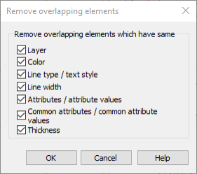
With this function, you can remove overlapping elements created via copying, for example. From the selected elements, only those that are exactly the same will be deleted.
You can choose not to compare some properties. If you choose not to compare layers, for example, the elements will be interpreted as similar if layer is the only difference.
Stickers – With this function, you can attach a "sticker symbol" in the drawing. The symbol is placed on zero layer, so that it is visible on each sheet of the schema application. Stickers can also be placed on printouts only by using the schema application queue printing function.