Create your own symbols
| Single-line tab > Devices group > |
With this function, you can create your own single-line symbols by exploding an existing symbol to be used as the base. This is also an easy way to get several attributes in your symbol. You can copy or edit the attributes as needed.
Do the following:
-
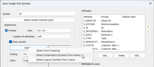
Enter a name for the symbol.
-
Select to draw the symbol framed or unframed:
-
Framed
-
There is a wiring point in the middle of each side of the frame. The top and bottom wiring points form a cut point pair, as well as the left and right wiring points.
-
The highest wiring point is the insertion point.
-
You can insert attributes inside the frame, to the right or left of the symbol, or above or below the symbol. Default attributes are located automatically. ID attributes are stacked automatically.
-
If you select Show symbol, you can select the symbol from the drawing, or from the Schematics or Layout menus with the Select button.
-
No Frame – You can select the symbol from the drawing, or from the Schematics or Layout menus. Wiring points and cut point pairs are left as they are but pin attributes removed.
-
-
If you want to insert wiring points to the symbol, do the following:
-
Below Wiring points, click Define.
-
Indicate the wiring points on the symbol.
-
Confirm the points by pressing Enter.
If you want to delete individual wiring points, click Delete, select the points that you want to delete, and press Enter.
If you want to delete all wiring points, click Delete all.
-
-
If you want to define some wiring points as cut points, do the following:
-
Insert at least two wiring points to the symbol by following the instructions of the previous step.
-
Below Cut points, click Define.
-
Select the first wiring point that defines the cutting line.
-
Select the second wiring point that defines the cutting line.
-
-
If necessary, select the symbol type and sub-types.
-
The default symbol type is Other, and the default sub-type Single-line Diagram Symbol.
-
If you selected a symbol, the symbol type is set accordingly and Single-line Diagram Symbol will be set as the sub-type.
-
Symbol type is not included in the E_ID attribute.
-
-
Select to create a horizontal or vertical symbol.
-
Edit the attributes of the symbol, and indicate the ID attribute insertion point, if necessary.
-
If the symbol has several overlapping attributes and you want to stack them, click Define and select the attribute definition that will be added to the stacked attributes.
-
Enter the tip text of the symbol that is visible when you hover the cursor over the icon in the icon menu.
-
Select whether you want to show the icon area manually. Otherwise, the program saves the area of the symbol's objects to the icon. This is the area that is visible in the icon menu.
-
If you want to edit the symbol, select the desired function from the Drawing and editing drop-down menu and click Run.
-
Click OK.
If you selected to show the icon area manually, the program opens the symbol in a new document tab.
Indicate the two corners of the area of the icon.
The program saves the symbol to the user icon menu. To access and insert the symbol, do the following:
-
From the Symbols menu, select User symbols. The icon menu with your own single-line symbols opens.
-
Insert the desired symbol in the drawing by double-clicking it and indicating the insertion point.
-
Stop inserting symbols by pressing Esc.