| Single-line tab > Other functions group > |
| Schematics tab > Other functions group > |
|
DB tool > Functions tab > Modular generate |
With modular generation, you can create full projects or parts of a project using modules and Excel module list. You can also use modular generation to add modules to existing projects.
Modules are small Electrical projects, which are saved to their own project folders. A module can be a drawing, a database or a full project. Typically, a single module holds only one function but it can vary case by case. A module can contain all Electrical objects, such as layouts, schematics, locations, devices, product information, I/Os, cables, plates, etc.
Generation also supports strip and block modules.
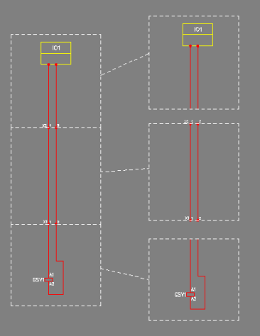
With block/strip modules you need less templates which helps to prevent mistakes. In addition, if you only need to make small changes you no longer need to duplicate templates.
-
A module can be smaller than one sheet. In practice, this means that different variations can be created with less modules.
-
The strips can be generated in a schema either vertically or horizontally, and the size can be defined separately for each strip.
-
If the X-Offset or Y-Offset column has a value in the Excel file, all the objects in the drawing are moved according to that value.
-
If the Sheet column has a value in the Excel file, the SLEHTI layer will be changed according to that value. Automatic sheet selection is then ignored in the merge as well, and the drawing is imported from the module as it is without changing the SLEHTI layers.
Unlike in a normal project, a module holds information that is parametrized with $$ links. You can parametrize texts in drawings, database texts, object IDs, etc. The same parameter can be used multiple times. When a module is generated, its parameters are filled according to an Excel module list.
Excel module list
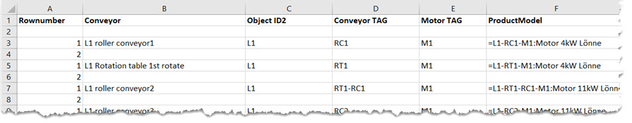
An Excel module list holds the information which will be used to fill the module parameters. Module info should be on the first worksheet. The columns on the first row should hold the parameter names. Only the Module parameter is mandatory, other parameters can be freely selected. In drawings and databases, the parameters will be referenced with the $$ links, for example "$ParameterName$" or "$ParameterName[Rownumber]$".
A module is treated as a strip/block module, if there is a value in the X-Offset, Y-Offset or Sheet column.
Parameters
Parameter names can be copied to the clipboard to be pasted to a drawing or to a database from the generation dialog by selecting a cell and pressing Copy to clipboard. Parameter can be assigned to a certain attribute in drawing by selecting the cell and pressing Assign to template drawing. You can select several cells, in which case they will be linked to the drawing one by one.

If an attribute in the drawing is read-only, you cannot link it.
There are few essential parameters listed below. You can use both the English and/or the Finnish parameter names (Finnish in brackets) regardless of the program's language.
-
Module (Moduuli)
- The only mandatory column.
- If it is a database module, you fill in a project folder.
- If it is a template drawing, you fill in the document name, e.g. "template.drw".
-
Rownumber (Rivinumero)
- With a row numbers it is possible to add data from multiple rows to a same module.
- In a template drawing or database row number is referenced with square brackets, e.g. "$ParameterName[RowNumber]$".
-
DrawingFile (Kuvatiedosto)
- Name of the drawing to be generated.
- If the column does not exist or is empty, the resulting drawing will be named after the template drawing(s).
- If you give the same name to multiple modules, you have to select Merge schemas -setting when generating the drawings.
- The name of the drawing file can also be parametrized, e.g. "$Location$-$Number$.drw", in which case the file name will be constructed from the columns Location and Number.
Note: In a case above you should not use the DrawingFile column because it will overwrite the drawing name parametrization.
-
I/O Channel...9 (I/O-kanava)
- Column determines in which I/O card channel the I/O tag will be connected.
- Same module can be used multiple times and increase the I/O channel number.
-
ProductModel...9 (Tuotemalli)
- Name of the product model to be attached to the device, for example for the device "=L1-RC1-M1" the product model could be attached with the value "=L1-RC1-M1:Motor 4kW Lönne".
- Device gets its product information, additional information, etc. from the product model.
- Product model can be located in a project database or in shared databases.
-
Connect...9 (Kytke)
- With this column it is possible to set or change cable's wire indexes.
- Can be used multiple times and increment cable's wire numbers (=indexes).
-
Selected (Valittu)
- Column is used to select the modules to generate.
- Values can be: X = selected, empty = not selected.
You can add several pieces of product information into the same cell with separators: {ID}:{Item code 1}*{Quantity 1},{Subcontract 1},{Spare part 1};{Item code 2}*{Quantity 2},{Subcontract 2},{Spare part 2};{Item code 3}, etc. For example, =123+MCC1-X1:123456*3;654321*1 adds product information 123456 three times and product information 654321 once to device X1.
The separators are:
| : | separates device ID from the item codes |
| ; | separates item codes from one another |
| * | separates quantity (optional) from the item code; default value is 1 |
| , |
separates subcontract / spare part information (optional) |
If a value includes separators, you need to use quotation marks around it, for example =123+MCC1-X1:123456*3,"Subcontractor: X, Y",SP1;654321*1,SC2,SP2.
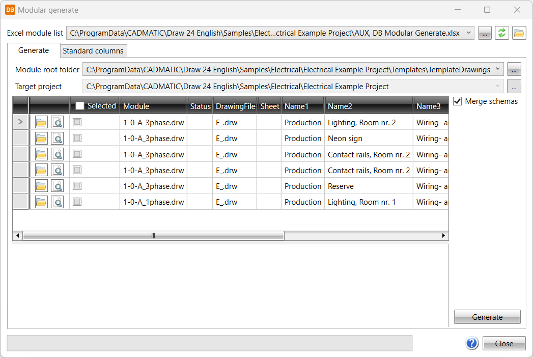
Generation
Do the following:
-
Open the target project, or create a new one.
-
Launch the function.
-
Select Excel module list by clicking the
 button. You can re-read the file by clicking the
  button,
or open it for viewing and editing by clicking the
button,
or open it for viewing and editing by clicking the  button.
If the module root folder is the same as previously, the previously used module list is used by default (unless the list has already been selected, for example, via the command line).
-
If you opened generation without any drawings open, select the project by clicking the button next to the Target project field. The module root folder is then added according to the default settings.
-
The selected module directory is interpreted as relative, if it is below the target project.
-
The selected module directory is saved in the target project settings.
-
-
In the Selected column, select modules to generate.
-
Click Generate.
If you selected Merge schemas and target files already exist, a warning about merging modules to the existing files is shown. Continue by clicking OK.
When generation is ready, you can open the files by clicking the links on the Documents tab in Electrical DB.
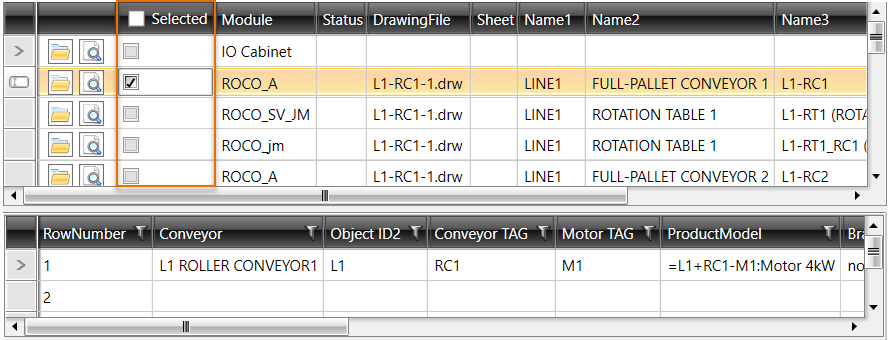
The DrawingFile column is highlighted in yellow if the file already exists.
Parameter names can be copied by selecting the parameter and clicking Copy to clipboard. By clicking Assign to template drawing, you can assign the selected cell's parameter to the drawing's attribute. You can select several cells, in which case they will be linked to the drawing one by one.
You can also carry out generation with the MODULARGENERATECMD command, after which you need to enter target project directory and the Excel file directory.