Do the following:
-
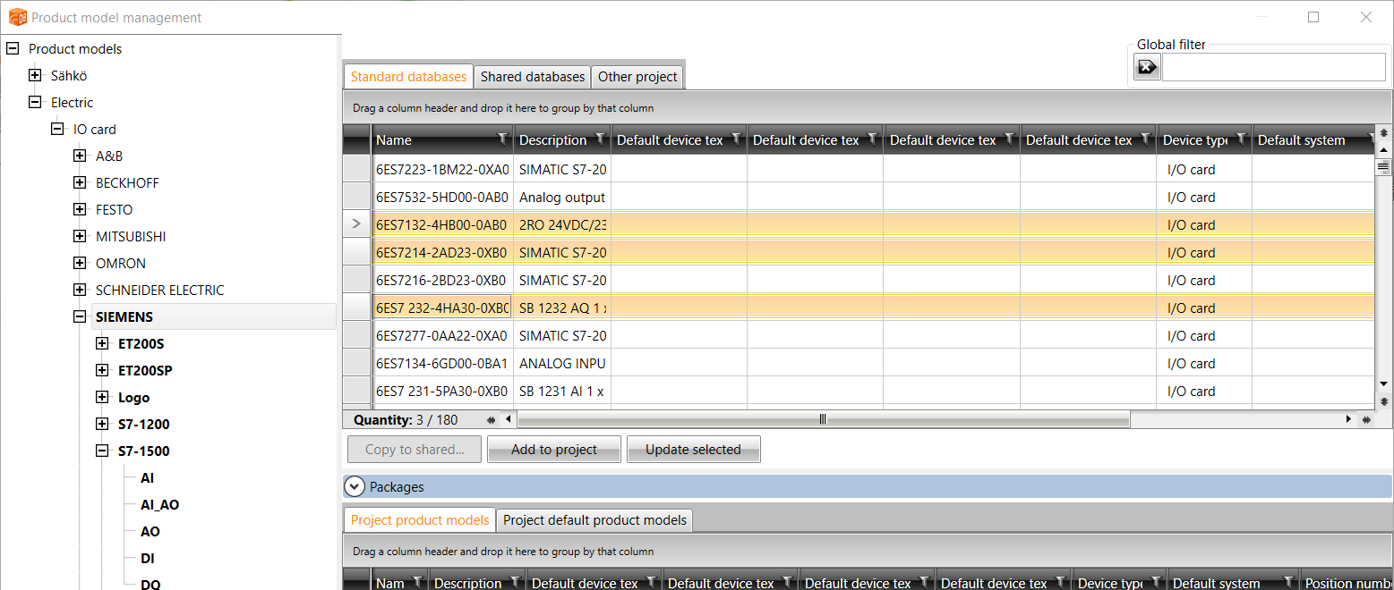
Open DB Tool, and select Management > Product models.
-
Add I/O card product models for the project by selecting the desired product models from the standard databases and clicking Add to project.

You can filter and search I/O cards by manufacturers, series or types in the Product models project tree or with the general column filters in the grid.
The standard product models include all the standard cards from the previous I/O configuration tool. If you cannot find the desired card from the standard databases, you can create a new product model in the project product models.
-
Before creating a new card, do the following:
-
Update the database changes to the drawing by clicking the project tree button
 (Sync changes from database to drawing).
 -
Insert a drawing frame, and define object ID =123 and electrical position +MCC1 for it.
-
Save the drawing.
-
-
Create a new I/O card:
-
Select Schematics tab > Devices group > I/O menu > Create I/O card. The New I/O card dialog opens.
-
Add the necessary information, for example:
-
Enter location =123+MCC1.
-
Create a new I/O rack by entering the ID A01. Alternatively, select an existing I/O rack from the drop-down menu.
-
Enter ID A1.
-
Select a product model added via product model management. Card description and channel information are automatically added according to the product model.
-
-
-
Add all the necessary information for the new I/O card. You can enter the information as follows, for example:
-
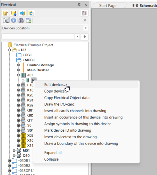
Select Devices (location) from the project tree.
-
Right-click the card you want to edit and select Edit device.

-
In the Device properties dialog, enter the necessary information for the card.
The I/O card properties section only includes I/O card specific information. When you enter the Start address IN or Start address OUT information, addresses will automatically be created for card channels.
-
After entering all the information, accept by clicking OK. The editing dialog is closed.
You can also add and edit I/O card information in the DB Tool, on the I/O cards tab.
The I/O channel addresses for the product models in the standard database are created based on manufacturer specific rules.
-
-
Create and insert I/Os to a drawing, and create I/Os connected to them.
-
Select Devices (location) from the project tree, and browse to the I/O card whose I/O channel occurrences you want to insert.
-
Right-click on the I/O card channel to be inserted, and select Insert I/O symbol into drawing.
-
Enter all the necessary I/O information.
The I/O automatically receives the following information from the I/O card:
-
Object ID
-
Electrical position
-
Address
-
Connector number(s)
-
Connector description(s)
-
Circuit code
-
Circuit number
The information from the I/O card is locked when inserting I/Os.
-
-
Enter an appropriate tag name and I/O texts.
-
Click OK.
The green icon shown for connected I/O channels means that it has been correctly connected to the I/O. A red icon, in turn, means that there are more than one I/Os connected with the same channel.
-
Repeat the steps described for other I/O channels. You can also create several cards whose I/O channels you then insert into drawings.

Because the I/O card in question has product model information, it automatically gets the symbol defined for the I/O channel from the product model. If the symbol for the product model channel has not been defined or the product model is not used, it needs to be entered when inserting the I/O.
After creating the I/Os, you can create an Excel report of them.
-
-
Create an Excel report:
-
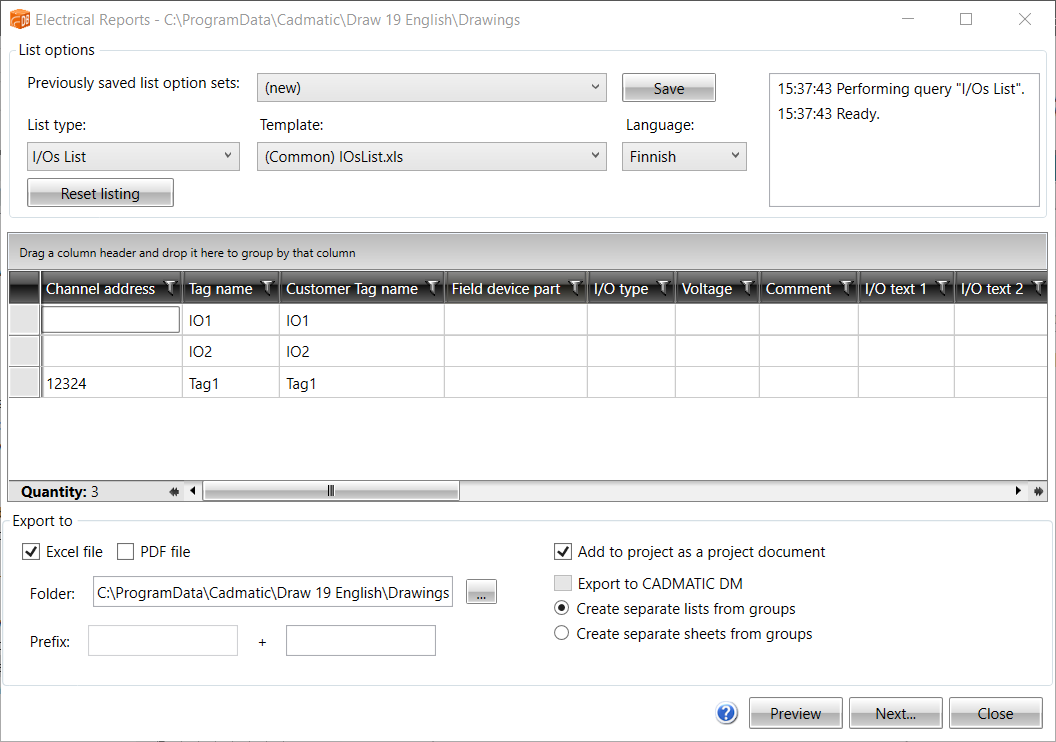
Select Electrical tab > Projects group > Reports menu > Reports.
-
As the report type, select I/Os List.
-
As the template, select (Common) IOsList.xls.
-
As the file type, select Excel.
-
As the folder, select the project folder.
-
Select Add to project as a project document.
-
Click Next.
You can view the report by opening it from the project folder or by selecting Documents from the project tree. To update the report to the project tree, click the
 (Sync changes from database to drawing) button.

Because the Excel report was added as a project document, you can update it automatically from the project tree by clicking Update report.
-