|
|
Electrical tab > Projects group > Project settings |
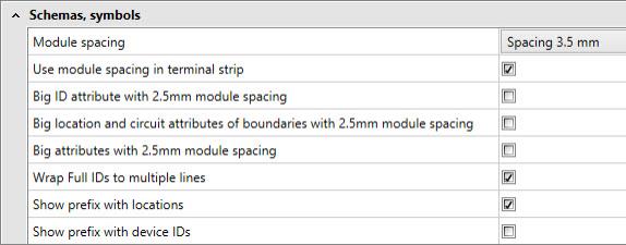
In the Schema, symbols section, define the size and appearance settings for wiring diagram symbols.

- Module spacing – This setting defines the spacing for wiring diagrams. Typically, the module spacing is 3.5 mm. If a drawing has been created by using module spacing of 2.5 mm, the same module spacing should be set. Then the symbols which is to be added in the drawing are reduced to correspond this spacing.
- Use module spacing in terminal strip – This setting affects drawing of the terminal strip and cable combing. If the setting is activated, the terminal strip will be drawn according to the spacing; the terminals will be drawn 3.5 mm wide with spacing 3.5 and 5 mm wide with spacing 2.5. If the setting is not activated, the terminal strip width is 4 mm. Then also the cable termination width is 4 mm.
- Big attributes with 2.5mm module spacing – Some symbols will be smaller, if module spacing is 2.5. If this setting is enabled, the ID-attribute sizes of these symbols won't be reduced.
- Wrap Full IDs to multiple lines – If this setting is on, will application separate IDs to different lines (max. 3 lines) when symbol is inserted in to drawing. This setting will expect that symbols have all these three ID attributes, E_OBJECTID, E_ELPOSID and E_ID. The division will be performed according to the following standard punctuation: =, + and -.
-
ID =TARG+POS-C1 will be divided as follows:
=TARG
+POS
-C1
-
+MCC1-Q1 will be divided as follows:
+MCC1
-Q1
- Show prefix with locations – If this setting is on, the standard punctuation ( = , +) is shown for location IDs.
- Show prefix with device IDs – If this setting is on, the standard punctuation ( = , + , - ) is shown for device IDs.