Create and insert symbol groups
Next, we will create and insert symbol groups into the drawing.
Do the following:
-
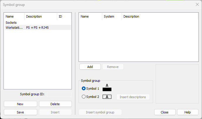
Select Layout tab > Devices group > Symbol functions menu > Symbol group. The Symbol groups dialog opens.
-
Click New. The New symbol group dialog opens.
-
Enter Workstation 1 as the name.
-
Enter PS + PS + RJ45 as the description.
-
Click OK.
-
Select the symbol group you just created from the left.
-
Select the symbols for the package:
-
Click Add.
-
In the Symbols window, select Electric > Plug sockets and double-click the Plug socket, 2-gang, protective contact, flush symbol.
-
Click Add.
-
In the Symbols window, select Electric > Plug sockets and double-click the Plug socket, 2-gang, data, flush symbol.
-
Click Add.
-
In the Symbols window, select Tele > Data and double-click the Data plug socket, flush mounting symbol.
-
-
Click Save.
-
In the Symbol group ID field, enter A.
-
Click Insert.
-
If necessary, rotate the package symbol by pressing F8.
-
Insert the package symbol in the middle of the vertical cableways using the Center or Midpoint snap.
-
Stop inserting package symbols by pressing Esc.
-
Select Symbol groups from the Symbol functions menu again. The Symbol groups dialog opens.
-
Click Insert descriptions.
-
Insert the descriptions in the drawing outside the building.
 Previous Previous |
Next

|