|
|
Schematics tab > Wiring group > Draw busbars |
|
|
Distribution Board tab > Wiring group > Draw busbars |
With this function, you can draw voltage supply and control voltage busbars. You can also use the function for three-phase drawing without IDs.
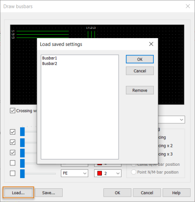
If you have already saved busbar settings, you can load them to the dialog with Load.
If you load the settings and then change them, the changes are not automatically saved; if necessary, save the settings by clicking Save and then overwriting the previous settings.
Draw a busbar as follows:
-
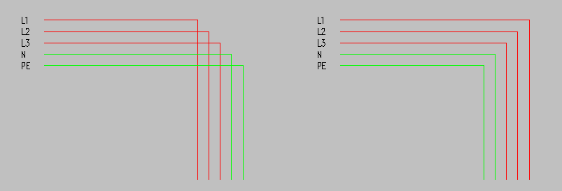
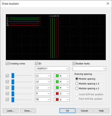
Select whether you want the wires to cross in the corners or not.
-
If you want to mark IDs to the busbars, select ID. If necessary, select the desired ID for the device from the drop-down menu or enter it in the field.
-
By default, the device ID is <SUPPLY>.
-
The ID drop-down menu lists all the devices with device type Power Busbar.
-
If you do not select ID, occurrences of the Power Busbar device will not be inserted in the drawing nor IDs for the busbars.
-
-
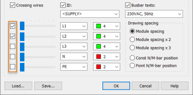
If you want to define a text to be shown in the drawing, select Busbar texts and then select the desired text from the drop-down menu or enter it in the field. The text is inserted as a device symbol.
-
Select how many busbars you want to draw.
-
Define the starting point of the busbars with the sliders.
-
If necessary, select busbar ID and color. The ID is enabled only if you selected the ID option in step 2.
-
Define the spacing:
-
Module spacing – 3.5 mm (the default defined in the settings)
-
Module spacing x 2 – 7.0 mm
-
Module spacing x 3 – 10.5 mm
-
Const N/M-bar position – When you selected to draw two busbars, the program places the N/M bar in a constant position.
-
Point N/M-bar position – When you selected to draw two busbars, you can indicate the position of the N/M bar.
-
-
If you want to save your settings for later, do the following:
-
Click Save. The Save new settings dialog opens.
-
Enter a name for the settings.
-
Click OK.
You can later load the saved settings in the dialog with Load.
-
-
Click OK.
-
Indicate the start point of the busbar. The drawing line follows the highest busbar line even if you selected not to draw it.
-
Indicate the next points of the busbar.
-
You can add chamfers to the corners of the wires with Tab.
-
You can change the wire spacing with Shift + Tab.
-
-
Stop drawing the busbar by pressing Esc or Enter.