Schematics tab > Wiring group > ![]() Edit menu > Define internal wirings automatically
Edit menu > Define internal wirings automatically
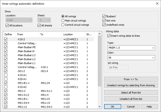
With this function, you can define internal wirings automatically. Function identifies lines/polylines as internal wires when both ends of lines/polylines are situated in the same location.

-
Only wires without wire data are listed.
-
When the wire is selected (= line selected in dialog), it is also colored with yellow in the drawing > to notice where the wire exist.
-
If wiring information from either end of the wire is missing, the wire is not selected (Define setting).
-
Terminal blocks side by side are not selected (e.g. X10:1 > X10:2).
Show
Location – All distribution boards or a single distribution board selected.
Sheet – All sheets or only one sheet selected.
All wirings – All distribution board's internal wires selected.
Main circuit wirings – Only main circuit wires selected. Function identifies main circuit wires by their color which is defined in Electrical settings. Green is the default.
Control circuit wirings – Only control circuit wires selected. Function identifies control circuit wires by their color which is defined in Electrical settings. Red is the default.
Wiring data
Insert wiring data to lines – Wiring data attributes are inserted to lines.
Type – Wire type (required)
Color – Wire color
1st wiring – Wires will numbered consecutively starting from the first wiring number.
Functions
From <> To – The From and To information can be reversed.
Unselect wirings by selecting from drawing – Internal wires will be shown in the drawing with turquoise color (color 5). Select wires which you don't want to define and accept selection by right-clicking.
Select all from list – All the wires get the Define setting.
Unselect all from list – All the wires lose the Define setting.