Visualization control

The Visualization Control toolbar button opens a menu for configuring the appearance of the 3D view.

Edges
-
No edges – Objects have no distinct edge lines. This is the fastest visualization mode and recommended for very large models.
-
Edges – Objects display feature edges (sharp edges and seams, such as welding joints).
Point clouds
-
Show point cloud scanner points – If selected, the point cloud scanner points are visible.
-
Points – Point clouds are visualized using points.
-
Splats – Point clouds are visualized using splats (slightly larger than points).
-
Show point cloud difference – Activates difference mode comparing the 3D model and the point cloud in visualization. The tool is not accurate and is only meant for visualization purposes. By default, the parts where the model and the point cloud differ less than the set tolerance value are highlighted with green. The parts found only in the point cloud are highlighted with red, and the parts found only in the 3D model are highlighted with blue. Grey areas are too far away from the camera and cannot be compared by visualization. The tolerance value and colors can be changed in Settings > Point clouds. See Point clouds.
Insulations
-
Hide insulations – Insulations are not visible.
-
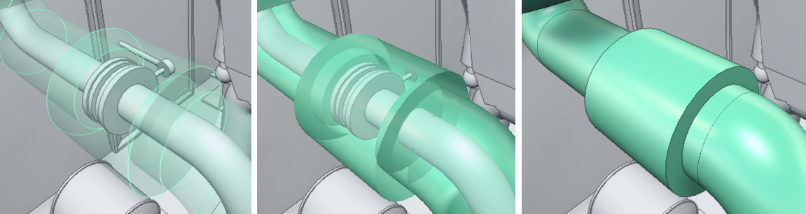
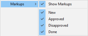
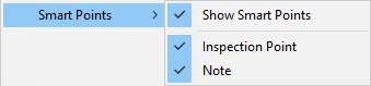
Show transparent insulations – Insulations are transparent. Objects that are inside or behind the insulation are clearly visible.
-
Show semitransparent insulations – Insulations are semi-transparent. Objects that are inside or behind the insulation are at least partially visible.
-
Show opaque insulations – Insulations are completely rendered. Objects that are inside or behind the insulation cannot be seen.
In this example, the left image displays transparent insulation, the middle image displays semitransparent insulation, and the right image displays opaque insulation:
Welds
-
Show welds – If selected, welds are visible.
Cable routing objects
-
Show cable routing objects – If selected, cable routing objects are visible.
Connection points
-
Show connection points – If selected and the model contains connection points, the connection points that are near the cursor are visualized. When in Examine Mode only the connection points of the examined object are shown. Moving the cursor over a connection points displays the node number.
Note: Snapping to connection points can be toggled on or off—see Measure.
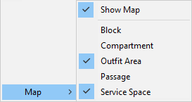
Markups
Select whether to show markups in the 3D view. If they are shown, you can select which statuses to display.
Smart Points
Select whether to show Smart Points in the 3D view and map. If they are shown, you can select which types to display.
Visual styles in legend
-
Show all visual styles in legend – If selected, the visual styles legend shows all visual styles. If not selected, only the visual styles of visible objects are shown.
Coordinates
-
Show coordinate display – If selected, the current camera coordinates are displayed at the bottom of the 3D view. By default it shows named coordinates, but if named coordinates are not available, Cartesian coordinates are shown instead.

-
Show coordinate marker – If selected, a main axis marker is displayed in the bottom-left corner of the 3D view.

-
Reference coordinate grid – Select whether to show the reference coordinate grid in the model. Coordinate planes must be defined in the model using CADMATIC Plant Modeller. By default you can toggle z plane grid visible by clicking the plane label in 3D view. If the selection in 3D view does not work, in Grid settings you can select which planes are visualized by first disabling Toggle z planes from 3D view and selecting the planes. This is helpful if the model contains a lot of reference planes and toggling labels from 3D view becomes complicated.

The color of the grid line can be configured in the Settings menu. See Visualization.
Measure can be enabled to be used with the coordinate grid in the Measure tool options. See Measure tool options.
-
Show object identification labels – If selected, the 3D view displays an identification label for the largest objects near the cursor. Pipes display the label along the centerline of the pipe, and other objects display it next to the center point of the bounding box.
In application settings you can list the attributes that these labels can use. Each label displays the value of the highest-priority attribute (or set of attributes) that can be found from the object in question. See Other options.
Map
You can select whether to show the model’s navigation map at the bottom of the 3D view. Depending on the model, there might be a number of different map types that allow you to choose whether to display blocks, compartments, service spaces, and so on.
When the navigation map is displayed, you can click the map to move the camera to the specified location. You can drag the upper-left corner of the map to resize the navigation map.
Smart Points and markups that are at the same floor or deck level as the user and inside the map area are shown in the navigation map.
For more information on maps, see Navigation map.
Show in VR
Show in VR opens the current eShare view in a separate Virtual Reality window. The window only shows the objects that are currently visible in eShare.
Note: VR view is available only in eShare App.
Using the VR view
You can open the eShare application window's view to a Virtual Reality headset (VR glasses) connected to the computer.
Prerequisites
- The Steam client and the SteamVR application by Valve. You can review the system requirements and download the application from the Steam store: https://store.steampowered.com/app/250820/SteamVR/.
- OpenVR headset such as HTC Vive, Oculus Rift, or Windows Mixed Reality.
Do the following:
-
Only the visible objects are displayed in VR. Showing fewer objects can make it easier to navigate and improves the performance—for best performance, send as few objects as possible to VR. Trying to open too many objects in VR at the same time shows a performance warning.
You can limit the number of objects to be shown by hiding the unnecessary objects or by using a clip box in eShare.
-
Navigate to the position from where you want to open the VR view.
-
Select Visualization Control > Show in VR. The CadmaticVR window opens and the active 3D objects are converted to the VR format (this can take some time).
Tip: If the VR does not seem to open, start the SteamVR application manually and then click Show in VR.
Now you can put on your VR headset.
-
You can use the VR controller to navigate in the model and select objects.
Note: Use the VR menu to switch between teleport mode (default) and normal movement.
Teleportation:
- Step forward by pushing the touchpad forward (shows a parabolic pointer) and then releasing it.
- Step backward by tapping the bottom of the touchpad.
- Rotate camera by pressing the side of the touchpad.
Movement:
- Move to a direction by tapping the touchpad. Move up or down by pressing the touchpad up or down.
- Rotate camera by pressing the side of the touchpad.
Object selection:
- Point the object with the VR controller and press the trigger button.
-
You can use a keyboard and mouse to navigate in the model and select objects.
Teleportation:
- Teleport to an object by right-clicking.
Movement:
- Move horizontally with W–A–S–D or arrow keys.
- Move up by pressing R or Space.
- Move down by pressing F or the left Ctrl key.
- Rotate camera with Q–E or by holding down the middle mouse button while dragging.
Tip: Default movement speed can be adjusted from the VR menu. Hold down the left Shift key to temporarily double your movement speed.
Object selection:
- Point and click with the mouse.
-
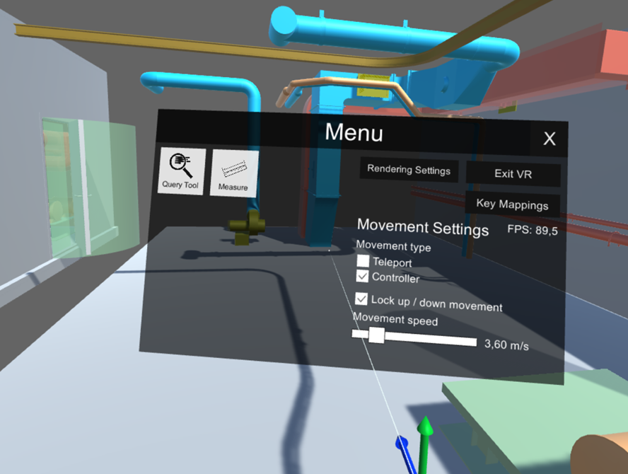
You can open the VR menu by pressing the VR controller's menu button or the Tab key.
The menu contains the following items:
-
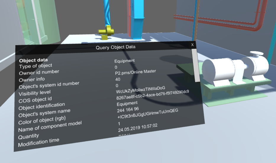
Query Tool – Allows viewing object data by pointing at an object and clicking. The Query Object Data dialog opens, showing the object attributes.
Note: Not all object attributes are shown in VR.
-
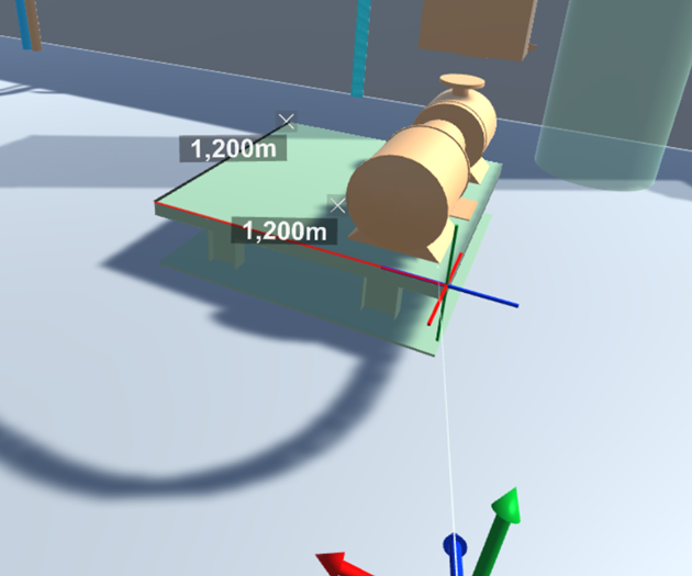
Measure – Allows taking measurements from the model by first pointing at an object and then clicking to select the first and the second measurement point.
You can specify the following settings:
- Snap to vertices – If selected, the measuring tool snaps to vertices.
- Snap to perpendicular – If selected, the measuring tool snaps to perpendicular lines.
Click Clear all measurements to remove all measurements from the VR view.
-
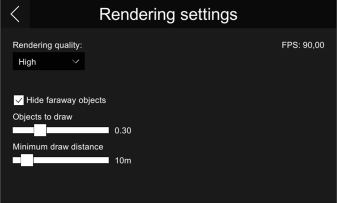
Rendering settings – These settings should be configured so that navigation is smooth at approximately 90 frames-per-second.
-
Rendering quality – Specify how detailed the VR view should be. Selecting higher rendering quality enables advanced features such as more detailed shadows, but it might decrease the performance.
-
Hide faraway objects – Hiding objects that are far away might improve the performance.
-
Objects to draw – Each model object is drawn using small triangles. This setting specifies the maximum amount of triangles to draw in "Hide faraway objects" mode. You can set the slider to a value between 0.1 – 1.0, where 1.0 means one million triangles.
-
Minimum draw distance – Objects that are closer than this value are always drawn, regardless of the "Objects to draw" setting.
-
-
-
Key Mappings – Allows changing the keyboard mappings.
-
Exit VR – Closes the CadmaticVR window.
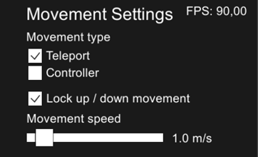
Movement Settings
-
Movement type – Specifies movement type when using the VR controller (does not affect keyboard/mouse).
- Teleport – If selected, using the touchpad teleports the view forward or backward.
- Controller – If selected, using the touchpad moves the view in the specified direction.
-
Lock up / down movement – Locks the movement to be horizontal only. When disabled, you can move freely in the model.
-
Movement speed – Specifies movement speed when using the VR controller or the W–A–S–D keys.
-
FPS – Displays the current frames-per-second count.
-
-
If you change object visibilities or move to a different camera position in eShare, you can update the open VR view by selecting the Show in VR command again.
-
Close the CadmaticVR window by selecting Exit VR from the VR menu. You can also press Esc to show the exit dialog.
Show in presentation mode
Presentation mode is a visualization mode deploying live-rendered ray tracing. Using it requires meeting certain system requirements. See Presentation Mode.
Note: Presentation mode is available only in eShare App.
Showing/hiding or selecting objects in presentation mode is not supported, so if any parts of the model need to be hidden in the model in presentation mode, this needs to be done in normal visualization before launching presentation mode.
Panning by holding the middle mouse button down or zooming with the mouse wheel do not work.
Many of the user interface features are disabled in presentation mode. The following features work in presentation mode:
-
In the sidebar Clip box tab is available.
-
In the main toolbar:
-
Move back or forward in navigation sequence
-
Navigation menu: all features except projection selection (Perspective projection is used) and Zoom to area
-
Settings:
-
Settings > View/Movement: only View angle and Moving speed have any effect.
-
Camera Location
-
Update Model works but reverts back to normal visualization
-
-
Scenes
-
Do the following:
-
Select Visualization Control > Show in Presentation Mode. Launch presentation mode dialog opens.

-
In the Launch presentation mode dialog, specify the following:
-
Select the mode:
-
Optimize for speed – The speed mode is the default and recommended choice, because it runs much faster (around 2x the frame rate when compared to the memory efficiency mode), but uses higher amount of VRAM.
-
Optimize for memory efficiency – Memory efficiency mode should be used if the user's GPU has a low amount of VRAM and are opening a large model. This mode runs much slower, but it allows opening larger models when limited by VRAM.
Note: The mode selection has no effect on the system RAM usage, only the GPU memory usage.
-
-
Generate metallic materials – This setting is used to control if some objects have shiny/mirror-like/metallic material. Some objects like cylinders, toruses, cones, and spheres are given metallic materials and the saturation of the original color controls the shininess. This means that the objects with metallic materials and the level of shininess may vary.
-
-
Select Launch. The dialog closes and the current model will start loading in presentation mode. The loading status is shown in a separate dialog. If all of the system requirements are not met, the loading will stop and display an error message. If the application runs out of GPU VRAM, first a warning is given, and then an error message if loading the model fails due to VRAM being full.
-
The presentation mode opens with a floating Settings dialog.

The Settings dialog has the following options specific to presentation mode:

-
Lighting
-
Sun – If enabled, the direct light from the sun is visible.
Note: Even when sun light is disabled, the atmosphere remains unchanged and provides some illumination that depends on the position of the sun.
-
Elevation – The elevation of the sun, measured from the horizon to the middle of the sun. The range is -10 - 90 degrees. A negative value means the sun is below the horizon.
-
Azimuth – The direction of the sun in xy-plane, where 0 is in direction of positive y-axis. The range is 0 - 360 degrees.
-
Spotlight – If enabled, a secondary light source is used.
-
Follow camera – If enabled, the spotlight is attached to the camera and moves with the camera. If disabled, the spotlight will remain in the current position when the camera is moved.
-
Luminosity – Controls the brightness of the spotlight. The brightness is exponential.
-
Spot cone – If enabled, the spotlight illuminates only in a conical direction. If disabled, it acts as a point light radiating in all directions.
-
Angle – Adjusts the angle of the spot cone (angular diameter). The range is 1 - 180 degrees.
-
-
Post-processing
-
Auto Exposure – If enabled, automatically adjusts the exposure of the current scene to become brighter or darker. It increases the brightness of the image in dark lighting conditions to make the environment more visible, and in bright conditions lowers the brightness to prevent clipping.
-
Tonemapping – Tonemapping here refers to the process of converting the internal rendered image that is in high dynamic range (HDR) into displayable standard dynamic range (SDR) image that is shown on the screen. There are multiple options for different tonemapping methods/algorithms: None, AgX, Filmic, ACES, Neutral, and Khronos PBR.Auto Exposure
-
Exposure – Adjusts the overall lightness or darkness of the colors. Primarily affects highlights. Applied before tonemapping.
-
Brightness – Alters the overall light level of the colors more evenly across shadows and highlights. Gentler adjustment than exposure. Applied after tonemapping.
-
Contrast – Increases or decreases the difference between the dark and light areas. Higher contrast makes the shadows darker and the highlights brighter, and lower contrast makes the view look flatter. Applied after tonemapping.
-
Saturation – Controls the intensity of the colors. Increasing saturation makes colors more vivid, and decreasing it moves colors toward gray. Applied after tonemapping.
-
Bloom – If enabled, a bloom effect is added to bright highlights to add to the perceived realism of the image.
-
Strength – Scales the intensity of the whole bloom effect.
-
Radius – Scales the size of the bloom effect around bright highlights.
-
-
Display
-
HDR10 – If enabled, enables output in High Dynamic Range (HDR) displays' HDR10 format with Rec. 2020 color space. This offers features such as higher contrast and a wider color gamut. To use this feature you must have a display with HDR support. Additionally, you must enable HDR in Windows display settings for the active display.
-
Max nits – Sets the maximum peak brightness for the outputted image in nits (cd/m²). You should set this value to the maximum peak nits of your display to avoid clipping or under exposure.
To reset settings, select Reset settings.
To view presentation mode in full screen mode, select Full Screen Mode. Click Esc key to exit full screen mode.
-
-
-
Select Exit Presentation Mode in Settings dialog to return to normal visualization.
Full screen mode
Opens the 3D view in full screen mode for model browsing. Click Esc key to exit full screen mode.