Drawing Properties
Construction > Properties

Displays and sets the properties of the current drawing. When a created view is saved, it becomes a drawing. The properties of the drawing can be modified here. Typical properties are:
- the area of the drawing
- the intersection value(s)
- the scale
- the display of the hull shape and/or the centre line
- the display of outfitting objects
The top part of the dialog shows the viewing plane. It sets the intersection value corresponding with the orthogonal viewing direction of the drawing. When the drawing concerns a slanted view, corresponding input fields that are used to define the position and angle of the viewing plane are activated.
Incorrect elements
When creating a new view by modifying the viewing plane values in the Drawing Properties, it may happen that the dimensions lose their relations and then the Incorrect elements panel pops up. The panel lists the dimensions and/or part numbers that have incorrect references.
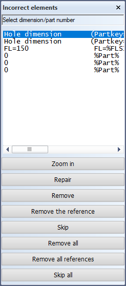
The dialog lists construction items present in the view for which no reference could be made. The dialog lists the part labels which could not automatically be repaired. There are two functions to repair the reference manually: Zoom in and Repair.
-
Zoom in – Displays the drawing at the position of the selected part label and its direct surroundings, and highlights the selected part label.
-
Repair – Indicate the construction part that qualifies for the selected part label.
-
Remove – Remove the selected incorrect dimension(s) completely. Now you can place new dimensions to replace the ones that lost their references.
-
Remove the reference – Remove the selected incorrect reference(s). The dimension itself will not be removed, but it will have no reference to any construction anymore.
-
Skip – Skip the selected incorrect item(s).
-
Remove all – Remove all incorrect dimensions completely. Now you can place new dimensions to replace the ones that lost their references.
-
Remove all references – Remove all incorrect references. The dimension itself will not be removed, but it will have no reference to any construction anymore.
-
Skip all – Skip all incorrect items.
Reference surface plane
This option appears when one or more reference planes are present in the hull shape database.
- Reference surface plane – Sets the plane definition of the drawing according to the selected reference plane. Drawings of this type receive a topological dependency with the selected reference plane. Plates created in these drawings receive the same topology.
- Distance – Gives the view an offset parallel to the reference plane while maintaining the topology. The view can be set to either side of the reference plane by using positive and negative values to determine the direction. The direction of a positive value is equal to the thickness direction stored in the reference plane. A negative value is in the opposite direction.
Origin – Sets the origin point of the drawing. By default this value is determined automatically in relation to the area limitation values. Changing this value manually can be useful when lining up multiple drawings of the same direction type, relative to the ship coordinates.
Scale – Sets the scale of the drawing.
Show construction
Sets the area limitation of the drawing for 3D construction items. The area can be set by typing in specific values in length, breadth and height direction.
- Show shell plates – Displays shell plates or the projection of shell plates in cross section.
- Show weld lines – Displays weld lines in the view.
Clicking the Visibility button opens the Visibility dialog, which contains settings regarding the presentation of construction parts in drawings.
- Set default visibility – Set all viewing distances to their respective default values.
- Distance in front of view – Set the viewing depth in front of the active drawing. When a construction item is farther removed from the view than the value specified here, it is not presented in the drawing. This option is used for plates, shell frames and brackets in cross section. It is not valid for face plates.
- Distance behind view – Set the viewing depth behind the active drawing. When a construction item is farther removed from the view than the value specified here, it is not presented in the drawing. This option is used for plates, shell frames and brackets in cross section. It is not valid for face plates.
- Hole distance in front of view – Set the viewing depth for holes in front of the active drawing. When a hole is farther removed from the view than the value specified here, it is not presented in the drawing. This option is used for holes in cross section. (Holes in plane view are displayed together with the plates they are in via the Plate distance settings.)
- Hole distance behind view – Set the viewing depth for holes behind the active drawing. When a hole is farther removed from the view than the value specified here, it is not presented in the drawing. This option is used for holes in cross section. (Holes in plane view are displayed together with the plates they are in via the Plate distance settings.)
- Pillar distance in front of view – Set the viewing depth for pillars in front of the active drawing. When a pillar is farther removed from the view than the value specified here, it is not presented in the drawing. This option is used for pillars in plane view.
- Pillar distance behind view – Set the viewing depth for pillars behind the active drawing. When a pillar is farther removed from the view than the value specified here, it is not presented in the drawing. This option is used for pillars in plane view.
- Plate distance in front of view – Set the viewing depth for plates in front of the active drawing. When a plate is farther removed from the view than the value specified here, it is not presented in the drawing. This option is used for plates (and their attributes), shell frames, brackets and face plates in plane view.
- Plate distance behind view – Set the viewing depth for plates behind the active drawing. When a plate is farther removed from the view than the value specified here, it is not presented in the drawing. This option is used for plates (and their attributes), shell frames, brackets and face plates in plane view.
- Pillar in section behind view – Set the viewing depth for pillars behind the active drawing not directly touching the plate in view. When the pillar falls within the entered viewing depth, but further than the value specified in Profile view distance, a marking symbol is presented indicating the position of the pillar. When a pillar is farther removed from the view than the value specified here, the marking symbol is not presented in the drawing.
- Maximum plate thickness for lines – Set the threshold for plates to be drawn with a double line presentation. When the thickness of a plate is higher than the entered value, the plate is presented with a default hatch or a colour fill pattern.
- Face plate view distance – Set the viewing distance for face plates behind and in front of the active drawing. This option is used for flanges only in plane view, and for face plates only in bulb view and in cross section.
- Profile view distance – Set the viewing distance for profiles behind and in front of the active drawing. This option is used for profiles and pillars in cross section.
- Equipment distance in front of view – Set the viewing depth for equipment in front of the defined outfitting box. When equipment is farther removed from the view than the value specified here, it is not presented in the drawing.
- Equipment distance behind view – Set the viewing depth for equipment behind the defined outfitting box. When equipment is farther removed from the view than the value specified here, it is not presented in the drawing.
- View direction towards – This option only appears for perpendicular views. Sets the view direction, which determines the direction in which you are viewing, relative to the angle of the active drawing.
- Foreship – Viewing direction from aft to fore.
- Aftship – Viewing direction from fore to aft.
- Starboard – Viewing direction from port side to starboard.
- Port – Viewing direction from starboard to port side.
- Top – Viewing direction from bottom to top.
- Bottom – Viewing direction from top to bottom.
Note: Distances in front of and behind views are relative to the current view and the selected view direction. This means that when the view direction is changed to the opposite side, construction that was originally positioned in front of the view is now behind it. Therefore such construction may no longer be visible depending on the distance that was originally set for behind the view.
Show shape
When selected, displays the hull shape in the drawing and sets the area limitation of the drawing for the hull shape. The area can be set by typing in specific values in length, breadth and height direction.
Show outfitting
Defines which outfitting objects are presented. When clicking Outfitting all outfitting elements are presented. The list may contain user-defined selection criteria to present outfitting with.
- Remove hidden lines – When selected, a hidden line removal on the Outfitting drawing is performed before it is included in the current drawing.
Grid lines
- Centre line – Displays the centre line in the view, if applicable. This line can only be seen in top views and certain slanted views. Position places the centre line at an offset value. When left empty, the centre line will be left at its default position.
- Base line – Displays the base line in the view, if applicable. This line can only be seen in frame views, side views and certain slanted views. Position places the base line at an offset value. When left empty, the base line will be left at its default position.
- Height line – Adds a height line to the drawing, according to the default height grid of the block.
- More grid lines – Opens a dialog where more grid lines can be added. Grid lines can be added for width (at the top, bottom, or a defined position) and height (to the left, right or a defined position). Step defines the interval at which the numbers along the lines are displayed.
Weld symbols – Displays weld symbols in the view.
Clicking OK applies all provided input and closes the dialog.