Rotate
Construction > Items > Face Plates > Modify > Rotate

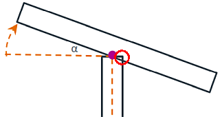
Rotate a straight face plate on plate. The rotation angle can vary from -60 degrees to 60 degrees.
Note: Bent face plates, face plates in holes, and face plates created with CADMATIC Hull version earlier than 2019T2 cannot be rotated.
Rotating a straight face plate on plate
Do the following:
-
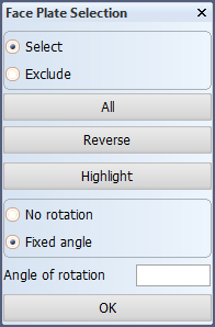
In the graphical window, select the face plate(s) to rotate.
- Use options Select and Exclude to either include or exclude items from the selection when you indicate them in the graphical window.
- All selects all the face plates in the drawing in one go.
- Reverse deselects the currently selected face plates, and selects the currently unselected face plates.
- Highlight highlights the currently selected items in the graphical window.
-
Select Fixed angle, and in Angle of rotation enter the rotation angle that is within the range of -60 to 60.
- Selecting No rotation removes the existing rotation.
-
Click OK to apply the rotation.
Note: The system will automatically recalculate the rotated face plate. However, the relations of the plate that the face plate is on are not automatically recalculated. You must recalculate the plate manually using the General > Recalculate function.
Face plate on a bevel
A bevel (standard or predefined) on a plate that the face plate is on is taken into account when the face plate is rotated. The position of the face plate is adjusted according to the bevel type.
Face plates on multiple plates
When the face plate is on multiple plates, the bevel on the main plate is considered. When the face plate is rotated in this case, it may happen that the face plate does not connect properly with one or more related plates after the rotation. In this case the system displays a warning.
Presentation of rotated face plates in drawings
Depending on the viewing angle, the rotated face plate will appear different in the drawing.
- From the side, where you defined the face plate, the face plate appears the same as before the rotation.
- Looking from the top, after rotation, the face plate appears narrower than before (how much, depends on the rotation angle).
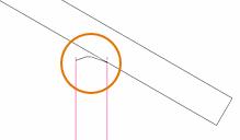
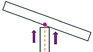
Rotation axis
The rotation axis is either at half the thickness of the main plate, or the moulded / thickness side of the plate, depending on whether the faceplate has a distance to the moulded side or not.
-
Face plate without a distance from the moulded side: The rotation axis is at half the thickness of the plate.
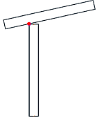
-
Face plate with a distance to the moulded side applied: The rotation axis is the side of the plate where the shorter part of the face plate is.
|
|
|
|
Rotation axis at half the thickness of the plate. |
Plate side as the rotation axis. |
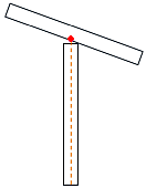 .
.Vertical shift
The rotated face plate is shifted away from the plate if the rotation would cause an overlap between the face plate and the plate.
|
|
|
|
Overlap between the rotated face plate and the plate. |
Shift to avoid the overlap. |
 .
.