Definition
Construction > Insert > Hull Line, Definition tab.
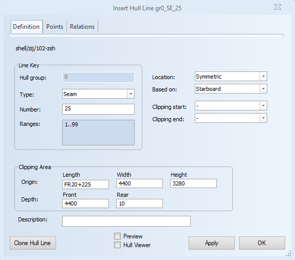
On the Definition tab of the Insert Hull Line dialog you set the definition of the hull line: The type of hull line, its line number, its location (starboard, port side, or both), and the hull group in which it will be drawn.
Line Key
Set the hull group, type, and line number of the hull line.
Hull group – Displays the hull group which was initially chosen for the hull line to be created in. The hull group cannot be edited.
Type – Sets the type of hull line to either Seam, Butt, or Dimension Line. Seams and butts always appear as solid lines and are always visible. Dimension lines become visible after they have been activated with the Show Hull Lines function.
Number – Sets the line number for the hull line. Each time Type is changed, a default value for the number is recomputed. The default value is the first available valid number found for the line. The number must meet the following requirements to be valid:
- It must be unique within the hull group and line type.
- It must be between 0.00 and 99999.99.
- It can have a maximum of two decimals.
- It has to be within the ranges available for the current user.
Ranges – Displays the ranges of line numbers available for the current user. For each selected line type, the corresponding ranges are displayed. Hull Line Ranges can be set in the System Management application.
Hull line Location
Set the location and visibility of the hull line.
Location – Sets the hull line to appear on starboard, port side or both. The location of a hull line determines where the line can be used (e.g. as a relation for another hull line, or for defining shell plates). A symmetric line can be used both on port and starboard sides, whereas a non-symmetric line can only be used on the side it is located.
For non-symmetric hull groups, the actual hull line is always located where the hull group of the line is (e.g. for a non-symmetric group located at starboard only, the hull line will also be located at starboard only). Therefore the field value cannot be changed and is set on the hull group's side.
This setting affects both the Hull Viewer model and the preview of the line.
Based on – Sets the hull line to be based on either starboard or port side for lines crossing the centre line. The default value is Starboard. Changing this value is relevant when the hull line is fully or partially drawn on port side. A hull line can be drawn across the centre line. However for computing the final line, only the starboard or the port side of the line can be used. This setting essentially indicates which side that will be.
For non-symmetric hull groups, the hull line is always based on the side where the line's hull group is. Therefore, in these cases, the field value cannot be changed and is set on the hull group's side.
This setting influences both the Hull Viewer model and the preview of the line.
Hull line limitation
Set the limitation of the hull line by using two relations. One for the start limit and one for the end limit. The final line will be the one between the start and the end limits. This limitation is named "clipping" and the relations used to limit the line are known as "clipping relations".
Clipping relations can be chosen from all existing relations (that is, the relations listed in the list of relations in the Relations tab).
Clipping start – Set the start limit for a hull line by selecting an existing relation. The start point of the final line is the first intersection point of the selected relation with the line. The hull line is not clipped if no intersection point is found between the two. The intersection point has to be closer along the hull line to the starting point than the intersection point used for the end clipping relation.
Clipping end – Set the end limit for a hull line by selecting an existing relation. The end point of the final line is the first intersection point of the selected relation with the line. The hull line is not clipped if no intersection point is found between the two. The intersection point has to be closer along the hull line to the ending point than the intersection point used for the start clipping relation.
Clipping Area
Define the geometrical space where the hull line is evaluated. This space is defined by an origin point with three coordinates and two depth values. The clipping area is therefore limited in depth direction, and unlimited in the other two dimensions (i.e., in length or height in side views). For a new hull line, default values are set, after which the clipping area will become independent of the view. Hull line relations are also clipped using the clipping area.
Origin – Sets the origin point of the clipping area by using grid coordinates. The default is the same as the origin of the view.
Depth – Sets the depth in millimeters in two directions; in front of the origin point and behind the origin point. The default in front is the total depth of the view. The default behind is 10 millimeters. Both directions accept only positive values.
Description
Sets a description for the hull line with the purpose of adding a custom distinction to the line.