Relations
Construction > Insert > Hull Line, Relations tab
In the Relations tab of the Insert Hull Line dialog you can create hull line relations either explicitly by indicating the desired item in the graphical window, or implicitly by entering a fixed value for the position.
In the context of creating hull lines, a relation is an element used to create a dependency between a hull line point and other objects.
You can create relations from items such as construction parts and existing hull lines.
Relations can be used in the following ways:
-
To create topological points and topological directions that make up a topological hull line.
Example: You want to create a point that is always 500 mm from the intersection of a deck with another construction part. When the deck or the construction part is changed, the point will also change. Therefore, the hull line will also change, making it dependent on the other two entities. -
To create clipping relations.
Example: You draw a hull line and you want the hull line to be limited by other existing hull lines that intersect it. You do this by creating relations from the existing hull lines, which will function as the boundaries that limit the hull line that you are creating.
Hull line relations can be created in the Relations tab and in the Points tab. In both tabs relations are handled the same way.
To create hull line and construction relations you must to indicate the desired relations in the graphical window.
The following hull line types can be used as relations: Angled curves, Knuckles, Dimension lines, Butts, and Seams.
When working with hull line relations, the following applies:
- Only hull lines belonging to the same hull group as the hull line using the relation can be used.
- Hull line relations are clipped with respect to the clipping area of the hull line being created.
- For symmetric hull lines, the system will use the part which is closest to the indicated point in the graphical window as the relation (starboard or port side).
- When creating hull line relations, the key of the line will be used for the default name and summary of the relation.
Construction relations are relations based on construction parts from the ship, such as plates, brackets and shell frames. For construction parts with thickness, the side which is indicated will be used as a relation. The same applies for a part that is located on both port side and starboard: Only the part that is indicated will be used as a relation.
When working with hull line relations, the following applies:
If the intersection with the hull results in more than one curve, only the closest curve to the indicated point in the graphical window will be considered. The relation will have a direction that is the same as the orientation of the indicated construction's contour.
Construction relations have a property called "1-vector". If this value is active, the relation is constructed as the intersection of an infinite plane through the construction part and the hull. For curved shell frames, the infinite plane is tangent to the shell frame in the vicinity of the indicated point.
Construction relations based on plates and brackets can be shifted. The displacement can be in 2D, with respect to the X and Y coordinates of the view, or in 3D using ship coordinates.
Note: When indicating starboard and port side construction parts in side views, it is recommended to set the viewing area of the drawing to the side on which the hull lines are drawn. For example, when indicating relations for a hull line that is drawn on starboard side, it is best to indicate a construction part that is also situated on starboard side. Regardless, it is still possible to indicate a construction part on port side, but the resulting relations might not perfectly align with the actual construction.
For fixed value relations, after the intersection with the hull, the relation can break into several curve segments. Because no point is indicated in the graphical window with this method, there is no information regarding which segment is intended to be used. Therefore the first curve segment will be used as default. However, a relation will be created for each resulting curve segment. A different curve segment can be selected in the relation properties area.
Points tab: You add a topological point by creating one or more relations for it. The relation is added to the relations list in the Relations tab. In case of creating a topological point that requires two relations, the relations are created once the second relation is selected. The Split button can be used for creating fixed value relations. Split becomes active only when topological points are selected in the points toolbar.
Relations toolbar
Manipulate the relations of the hull line. The relation properties can be changed in the properties area.
Add relation – Adds a new relation when a construction part (plate, bracket, shell frame) or another hull line is indicated in the graphical window. The relation can be further used for desired actions.
Replace relation – Replaces the selected relation with a new relation. The new relation will have the properties of the relation it replaces. The name will be kept if the name of the old relation was not the default name.
Highlight relation – Indicates the selected relation in the graphical window by temporarily changing the color of the relation.
Duplicate relation – Creates a new relation having the same properties as the relation being duplicated. The name of the new relation is based on the one being duplicated.
Delete relation – Removes the selected relation from the hull line. Only relations that are not used in the definition of the line (e.g. to build topological points) can be removed.
Remove all unused relations – Removes all relations that are not required by the current specification (e.g. to build topological points).
Split button with input field for fixed value relations
Create relations by entering a fixed value position in length, width or height direction. The result will be an intermediate hull line on the hull, passing through the fixed given value.
Select the direction with the arrow button. When the arrow is clicked, the value entered in the edit field is translated into coordinate values for the selected dimension, after which the relation is created. Alternatively you can press Enter. The relation appears in the graphical window, and in the list view. If the intersection with the hull results in more than one curve, a relation is added for each curve.
Relations list
Displays a list of all the existing relations and some of their properties. The displayed properties are as follows:
-
The type of relation by means of a symbol
-
An automatically created unique name which can be modified
-
A summary with some information about the related entity. See Default names and summaries below.
-
The state of evaluation which indicates if the evaluation of the relation was successfully done.
The default name of the relation contains information relevant to the type of the relation:
- For construction relations, the name refers to the construction.
- For hull line relations, the name refers to the key of the hull line.
|
Relation type |
Default name |
Summary |
|
Plate |
PL37 <MyBlockName> |
Plate 37 in block <MyBlockName> |
|
Shell frame |
PR38 <MyBlockName> |
Shell frame 38 in block <MyBlockName> |
|
Bracket |
BR39 <MyBlockName> |
Bracket 39 in block <MyBlockName> |
|
Hull line |
gr0_SE_301.5 |
gr0_SE_301.5 |
|
Fixed Value |
L FR14 |
Fixed length FR14 |
|
Fixed Value |
W -500.75 |
Fixed width -500.75 |
|
Fixed Value |
H 2000 |
Fixed height 2000 |
Relation properties area
Allows browsing and editing the properties of a relation. The properties are displayed as categories that can be hidden and shown by collapsing and expanding the categories.
Each category contains a list of properties with items for the selected relation. The items displayed change with the relation type. All edited fields are displayed in bold. If multiple objects have been selected, editing of the properties of all selected objects is allowed.
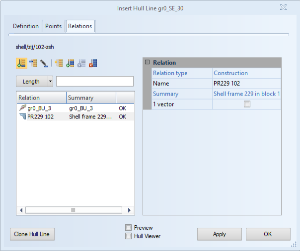
Relation – Displays the type, name, and summary of the relation. The name can be edited at any time. The default name of a relation refers to the name or key of the indicated item.
Surface displacement – Changes the position of a relation. Available only for construction relations. Displacements can be performed before or after the related item is intersected with the hull shape. The resulting displacement can be a combination of a shift with respect to the X and Y coordinates of the graphical window, and a shift with respect to the ship coordinate system. The shifting for the latter is done in millimeters, unless the value entered is a length value below 50. The coordinate that is not visible in the active view is not displayed. This is automatically assumed to be 0.