Show Hull Lines
Tools > General > Show Hull Lines
Add extra hull lines to the active drawing. Adding extra hull lines can provide a clearer image of the shape of the ship's hull. Extra hull lines can also be used to emphasize key positions of construction, or to indicate otherwise important positions within the ship.
The Show Hull Lines dialog lists the hull line types: angled curves, knuckles, dimension lines, frame lines, buttocks/verticals, water lines, hull boundary lines, groups intersections, butts, and seams. See Hull line types below.
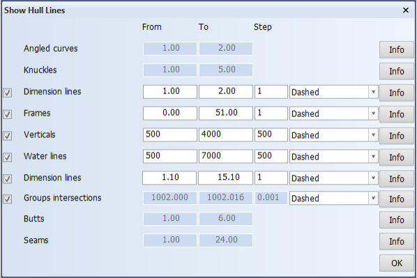
Select the hull line types that you want to add to the graphical window.
By setting a range (From, To) you can control at which positions the lines are added. See Hull line ranges below.
It is also possible to retrieve detailed information of each hull line present in the shape database. Click the Info button next to the hull line type to open a separate window showing this information in a table format.
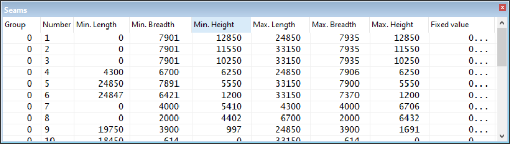
- Group – The number of the hull group which the line is a part of
- Number – The line number of the hull line
- Min. Length – The starting length position of a line in millimeters
- Min. Breadth – The starting breadth position of a line in millimeters
- Min. Height – The starting height position of a line in millimeters
- Max. Length – The ending length position of a line in millimeters
- Max. Breadth – The ending breadth position of a line in millimeters
- Max. Height – The ending height position of a line in millimeters
- Fixed value – The fixed position of a line. This is the position where the starting and ending positions of a line are the same value. Depending on the type of hull line, this can be a length, breadth or height value. If a line does not have a fixed position, this is indicated by a row of asterisk symbols.
Click OK to apply all provided input and close the dialog.
Hull line types
The Show Hull Lines dialog lists the hull line types currently present in the shape database, and provides the ability to select hull line types to be added to the drawing.
The hull line types are as follows:
-
Angled curves – These lines border flat areas to curved surfaces. They come with the external shape database and are always shown. Angled curves are designated by number in ascending order.
-
Knuckles – These lines border curved surfaces. They come with the external shape database and are always shown. Knuckles are designated by number in ascending order.
-
Dimension lines – These lines are primarily used as support lines in curved surfaces. They may have either come with the external shape database, or have been created in the Shell application and are stored in the user shape database. In both cases they are optional lines. When dimension lines are present in both the external and user shape databases, they will appear in the hull line list twice, and can be separately added to the drawing. Dimension lines are designated by number in ascending order.
-
Frames – These lines are drawn in length direction. They can indicate the frame positions, but can also be drawn at any desired length position. Their curvature is determined by the surfaces in the external shape database which they are projected onto. Frames are designated by frame number in ascending order.
-
Verticals – These lines can be drawn at any desired breadth position. Their curvature is determined by the surfaces in the external shape database which they are projected onto. Verticals are designated by their position in millimeters in ascending order.
-
Water lines – These lines can be drawn at any desired height position. Their curvature is determined by the surfaces in the external shape database which they are projected onto. Water lines are designated by their position in millimeters in ascending order.
-
Dimension lines (hull boundary lines) – These lines are a special type of dimension lines on the outer edges of hull groups. They also exist at the boundaries of adjacent hull groups, each hull group having its own boundary line at the hull group border. Hull boundary lines have numbers starting from 1.1. Decimal .1 indicates that the line is a boundary line. Subsequent lines are numbered using an increment of 1 (1.1, 2.1, 3.1, ...).
-
Groups intersections – These lines are located at the intersections of the shapes of hull groups. Two intersecting hull group shapes get identical groups intersection hull lines along their intersecting shapes.
Group intersection line numbers are expressed as <intersecting_groupnumber>.<line_number>, where the first part is the hull group with which the current group is intersecting, and the second part is the line number. The first part can be up to 4 digits, and the second part is 3 digits. In the case of intersecting hull groups 1 and 2, 2.001 is line number 1 in group 1, and 1.001 is line number 1 in group 2. Line number 100 in group 2 would be 1.1.
-
Butts – These lines primarily border shell plates in length direction. They may have either come with the external shape database, or have been created in the Shell application and are stored in the user shape database. These lines are always shown. Butts are designated by key number in ascending order.
-
Seams – These lines primarily border shell plates in breadth and/or height direction. They may have either come with the external shape database, or have been created in the Shell application and are stored in the user shape database. These lines are always shown. Seams are designated by key number in ascending order.
Hull line ranges
Set the range where lines are added to the drawing. The values are hull line numbers, except for vertical and water lines they designate the area.
-
From – The starting value of the range
-
To – The end value of the range
-
Step – The interval at which the lines are added. For dimension lines and frames "1" equals one line. For verticals and water lines "1" equals one millimeter.
-
Line type – Set how the lines should appear on the drawing: dashed or solid.
Note: The range cannot be set for Group intersections. When this option is selected, all the groups intersection lines that belong to hull groups that are set to be visible in the view are shown. Hull group visibility is set in Drawing Properties with the Hull groups selection.