Dimensions
Construction > Profiles > Dimensions
Both the metric and imperial unit system are supported in the dimension settings for profiles. It is recommended to enter the dimensions in only one unit system for a specific profile type.
By default, all profile dimensions are displayed in the unit system set for the project. Other than the project–wide unit system can be set for specific profile types in Construction > Profiles > Dimension Unit System. These settings override the project–wide setting.
Entering the dimension values
The dimesion values can be entered as plain numbers. Fractions (1/4) can be used, and a dot as a decimal point.
It is possible to enter the values in other unit system than the one set for the project or the profile type by using the following notations:
-
To enter metric values (mm), type mm after the numeric value. For example, 12mm.
-
To enter imperial values (inches), type " (double quotes) or ' (single quote) after the value. For example, 5", 1/2", 0.2'.
When the metric unit system is set, all values without quotes or double quotes are considered to be in millimeters. Similarly, when the imperial unit system is set, all values without the mm notation are considered to be in inches.
The Name field which is available for some profile types also supports using the mm, " and ' notations.
Profile Types
- Holland Profile (HP)
- Equal Angle Profile (HG)
- Unequal Angle Profile (HO)
- Half Round Profile (HR)
- Round Bar Profile
- HEA Profile
- HEB Profile
- HEM Profile
- INP Profile
- IPE Profile
- UN Profile
- UP Profile
- Square Pipe Profile (Duct)
- T-Bar Profile
- Square Profile
- Flat Bar Profile
- Corrugation Profile
- Pipe
- Web Profile
- Dimensions For HO And T-Bar
- Corrugation Stiffener
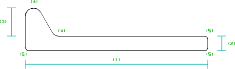
Holland Profile (HP)
The list contains all dimensions that can be selected when creating a Holland profile (HP).
The settings file for HP profiles differs from those for the other profile types, because in addition to the menus generated with this file, the models for presenting HP profiles in section should also be created.
To create a proper model that will closely resemble the actual profile, three additional values must be entered for each HP profile, besides body size and profile thickness. The complete data for HP profiles should include the following:
- Body size
- Thickness
- Bulb breadth (excluding the profile thickness)
- Radius of the end of the bulb, and radius at the bulb-body attachment
- Rounding radius of the corners
This setting also specifies dimensions for face plates in the 3D-Contek application. For the 2D-Contek application, these dimensions can be defined with the setting Construction > Face Plates/Flanges > Face Plate Dimensions (2D-Con.).
Equal Angle Profile (HG)
The list contains all dimensions that can be selected when creating an equal angle profile (HG). By using the toggle button instead of setting a value, it is possible to define that dimension value.
This setting also specifies dimensions for face plates in the 3D-Contek application. For the 2D-Contek application, these dimensions can be defined with the setting Construction > Face Plates/Flanges > Face Plate Dimensions (2D-Con.).
Unequal Angle Profile (HO)
The list contains all dimensions that can be selected when creating an unequal angle profile (HO). By using the toggle button instead of setting a value, it is possible to define that dimension value.
Depending on the settings for Unequal Angle Profile (HO) and T-Bar Profile, Flange Thickness could also be defined.
This setting also specifies dimensions for face plates in the 3D-Contek application. For the 2D-Contek application, these dimensions can be defined with the setting Construction > Face Plates/Flanges > Face Plate Dimensions (2D-Con.).
Half Round Profile (HR)
The list contains all dimensions that can be selected when creating a half round profile (HR). By using the toggle button instead of setting a value, it is possible to define that dimension value.
This setting also specifies dimensions for face plates in the 3D-Contek application. For the 2D-Contek application, these dimensions can be defined with the setting Construction > Face Plates/Flanges > Face Plate Dimensions (2D-Con.).
Round Bar Profile
The list contains all dimensions that can be selected when creating a round bar profile. By using the toggle button instead of setting a value, it is possible to define that dimension value.
This setting also specifies dimensions for face plates in the 3D-Contek application. For the 2D-Contek application, these dimensions can be defined with the setting Construction > Face Plates/Flanges > Face Plate Dimensions (2D-Con.).
HEA Profile
All available HEA profiles are listed in the overview.
The number value in the first column identifies a specific profile, and the profile's dimensions are defined in the next columns in the same row.
When creating an HEA profile, the user can select from all available profile numbers. The dimensions are not shown.
HEB Profile
All available HEB profiles are listed in the overview.
The number value in the first column identifies a specific profile, and the profile's dimensions are defined in the next columns in the same row.
When creating an HEB profile, the user can select from all available profile numbers. The dimensions are not shown.
HEM Profile
All available HEM profiles are listed in the overview.
The number value in the first column identifies a specific profile, and the profile's dimensions are defined in the next columns in the same row.
When creating an HEM profile, the user can select from all available profile numbers. The dimensions are not shown.
INP Profile
All available INP profiles are listed in the overview.
The number value in the first column identifies a specific profile, and the profile's dimensions are defined in the next columns in the same row.
When creating an INP profile, the user can select from all available profile numbers. The dimensions are not shown.
IPE Profile
All available IPE profiles are listed in the overview.
The number value in the first column identifies a specific profile, and the profile's dimensions are defined in the next columns in the same row.
When creating an IPE profile, the user can select from all available profile numbers. The dimensions are not shown.
UN Profile

All available UN profiles are listed in the overview.
The number value in the first column identifies a specific profile, and the profile's dimensions are defined in the next columns in the same row.
When creating a UN profile, the user can select from all available profile numbers. The dimensions are not shown.
UP Profile


All available UP profiles are listed in the overview.
The number value in the first column identifies a specific profile, and the profile's dimensions are defined in the next columns in the same row.
When creating a UP profile, the user can select from all available profile numbers. The dimensions are not shown.
Square Pipe Profile (Duct)
The list contains all dimensions that can be selected when creating creating a square pipe profile (duct). By using the toggle button instead of setting a value, it is possible to define that dimension value.
T-Bar Profile
The list contains all dimensions that can be selected when creating creating a T-bar profile. By using the toggle button instead of setting a value, it is possible to define that dimension value.
Depending on the settings for Unequal Angle Profile (HO) and T-Bar Profile, Flange Thickness could also be defined.
Square Profile
The list contains all dimensions that can be selected when creating creating a square profile. By using the toggle button instead of setting a value, it is possible to define that dimension value.
Flat Bar Profile
The list contains all dimensions that can be selected when creating a flat bar profile. By using the toggle button instead of setting a value, it is possible to define that dimension value.
This setting also specifies dimensions for face plates in the 3D-Contek application. For the 2D-Contek application, these dimensions can be defined with the setting Construction > Face Plates/Flanges > Face Plate Dimensions (2D-Con.).
Corrugation Profile
The list contains all dimensions that can be selected when creating a corrugation profile. By using the toggle button instead of setting a value, it is possible to define that dimension value.
Depending on the setting for Corrugation Stiffener, the thickness could also be defined. If the thickness cannot be specified, the plate thickness is used when creating a stiffener.
Pipe
The list contains all dimensions that can be selected when creating a pipe. By using the toggle button instead of setting a value, it is possible to define that dimension value.
Pipe creation is only available in the Insert > Pillars > Horizontal Pillars and Insert > Pillars > Vertical Pillars functions in the 2D-Contek and 3D-Contek applications.
This setting also specifies dimensions for face plates in the 3D-Contek application. For the 2D-Contek application, these dimensions can be defined with the setting Construction > Face Plates/Flanges > Face Plate Dimensions (2D-Con.).
Web Profile
The list contains all dimensions that can be selected when creating a Web profile. By using the toggle button instead of setting a value, it is possible to define that dimension value.
Web profile creation is available only in the 2D-Contek application.
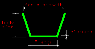
Dimensions For HO And T-Bar
Normally three dimensions are required to define an Unequal Angle Profile (HO) or a T-Bar Profile. With this setting, the amount of required dimensions can be set to four.
- 3 dimensions – Profile dimensions are Body size, Thickness, and Flange breadth.
- 4 dimensions – Profile dimensions are Body size, Thickness, Flange breadth, and Flange thickness.
IMPORTANT: If this setting is modified, the setting for the Unequal Angle Profile (HO) is opened automatically for adding or removing a fourth dimension to/from all available list entries. The adding/removing should also be done (manually) for T-Bar Profile dimensions.
Corrugation Stiffener
Normally three dimensions are required to define a stiffener with the Corrugation Profile setting. With this setting, the number of required dimensions, and the presentation (by a model or by lines), can be set.
- 3 dimensions, lines – The stiffener is drawn using lines.
- 4 dimensions, lines – A fourth dimension (thickness) can be used, presentation using lines.
- 3 dimensions, model – The stiffener is represented by a model.