Flanges
Production > Plate Cutting Data > Flanges
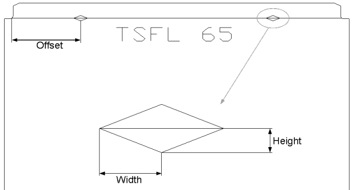
When a flange bending line is marked on the part, one or two markings can be placed along the line. The width, height and offset of the marking are specified by the settings here. If the width or height is set to 0, no markings are created. When the flange bending line is longer than a certain length, the system will create two markings, as shown in the image below. Otherwise only one marking is created at the middle of the bending line. This length can be also be specified.
Use Lengthening
When enabled (default), constructions are calculated with lengthening for flanges. If disabled, constructions are calculated without lengthening.
Flange Text Prefix, This Side
Set the text preceding the flange size used to indicate this side. Use double quotes around the text if the text contains a space.
If this setting ,and the Flange Text Prefix, Other Side setting are defined, the Flange Bend Text setting is overridden.
Flange Text Prefix, Other Side
Set the text preceding the flange size used to indicate the other side. Use double quotes around the text if the text contains a space.
If this setting and the Flange Text Prefix, This Side setting are defined, the Flange Bend Text setting is overriden.
Flange Text Postfix, This Side
Set the text following the flange size used to indicate this side. Use double quotes around the text if the text contains a space.
If this setting and the Flange Text Postfix, Other Side setting are defined, the Flange Bend Text setting is overridden.
Flange Text Postfix, Other Side
Set the text preceding the flange size used to indicate the other side. Use double quotes around the text if the text contains a space.
If this setting and the Flange Text Postfix, This Side setting are defined, the Flange Bend Text setting is overridden.
Flange Bend Text
Define the texts that can be placed along the flanges's bend line. The bend line identifies the side that the flange should be bent to.
The first text is used to indicate the viewing side, and the second text the non-viewing side.
This setting can be disabled by the term 'off'.
If one of the following combinations of settings are defined, this setting is overridden:
- Flange Text Prefix, This Side and Flange Text Prefix, Other Side
- Flange Text Postfix, This Side and Flange Text Postfix, Other Side
Show Flange Size
If enabled, the size of a flange will be visible along the bend line.
Radii In Contour Flange-Part
Select from the fixed, client-specific production parameters. The default value is no radii (default). It is also possible to select 5 mm.
Client-specific setting values are production parameters that depend on the yard's production potential and possibilities. The table below lists the setting values for each client. The values cannot be changed by the user. They can only be changed by Cadmatic at the client's request. The settings are usually discussed and agreed upon by Cadmatic and the client when the Hull system is to be taken into use.
| Client | Internal Value | Lower Die Radius | Attachment Radius | Outer Side | Bend Line | Lengthening | ||||
|---|---|---|---|---|---|---|---|---|---|---|
| From | To | Radius | From | To | Radius | |||||
| Abeking & Rasmussen | ABRA | 0 | 3 | 3,7 | 0 | ∞ | 10 | Yes | Yes | Always |
| 3,1 | 6 | 6 | ||||||||
| 6,1 | 7 | 7,5 | ||||||||
| 7,1 | ∞ | 9 | ||||||||
| CanAm | CANAM | 0 | ∞ | 2*thickness | 4,76 | Yes | Yes | Flange Dependent | ||
| Ching Fu Shipbuilding Co. Ltd. | CHINGFU | 0 | 8 | 12 | 0 | ∞ | 3*thickness, 0 if no lengthening |
No | Yes | Flange Dependent |
| 8,1 | 11 | 15 | ||||||||
| 11,1 | ∞ | 9 | ||||||||
| CI standard Aluminium | CISA | 0 | 10 | 20 | 0 | ∞ | 5 | No | No | Flange Dependent |
| 10,1 | ∞ | 2*thickness | ||||||||
| CS settings WPM | ECG | 0 | 10 | 20 | 0 | ∞ | 5 | No | No | Flange Dependent |
| 10,1 | 16 | 30 | ||||||||
| 16,1 | ∞ | 50 | ||||||||
| Damen Shipyards | DAMEN | 0 | 5 | 8 | 0 | ∞ | 15 | Yes | Yes | Flange Dependent |
| 5,1 | 6 | 12 | ||||||||
| 6,1 | 9 | 18 | ||||||||
| 9,1 | 14 | 28 | ||||||||
| 14,1 | ∞ | 45 | ||||||||
|
Dekc Maritime
|
DEKC
|
0 |
10,0 |
20 |
0
|
∞
|
5
|
No
|
Yes
|
Flange Dependent |
|
10,1 |
16,1 |
30 |
||||||||
|
16,1 |
∞ |
50 |
||||||||
| Drydock World Dubai | DDWD | 0 | 5 | 8 | 0 | ∞ | 10 | No | Yes | Flange Dependent |
| 5,1 | 8 | 12 | ||||||||
| 8,1 | 10 | 18 | ||||||||
| 10,1 | ∞ | 28 | ||||||||
| Estleiros Navais De Viano do Castelo | ENVC | 0 | ∞ | 0 | 0 | ∞ | 5 | Yes | No | No |
| Farwest | FARWEST | 0 | ∞ | 3*thickness | 0 | ∞ | 4,76 | Yes | Yes | Flange Dependent |
| Flensburger Schiffbau Gesellschaft | FSG | 0 | 8 | 12 | 9 | ∞ | 15 | No | No | Flange Dependent |
| 8,1 | 11 | 15 | ||||||||
| 11,1 | ∞ | 19.5 | ||||||||
| Gondan Shipbuilders | AG | 0 | 1 | 1,41 | 0 | ∞ | 20 | Yes | Yes | Always |
| 1,1 | 1,5 | 2,12 | ||||||||
| 1,6 | 2 | 2,82 | ||||||||
| 2,1 | 2,5 | 3,57 | ||||||||
| 2,6 | 3 | 4,25 | ||||||||
| 3,1 | 4 | 5,63 | ||||||||
| 4,1 | 5 | 7,2 | ||||||||
|
5,1 |
6 |
8,41 |
||||||||
|
6,1 |
7 |
9,8 |
||||||||
|
7,1 |
8 |
11,19 |
||||||||
|
8,1 |
9 |
12,59 |
||||||||
|
9,1 |
10 |
13,98 |
||||||||
|
10,1 |
12 |
16,78 |
||||||||
|
12,1 |
15 |
20,98 |
||||||||
| 15,1 | 18 | 25,17 | ||||||||
| 18,1 | ∞ | 2*thickness | ||||||||
| HLSDC | HALONG | 0 | ∞ | 15 | 0 | ∞ | 20 | No | Yes | Flange Dependent |
| IHC Holland Dredgers | IHC | 0 | 6 | 6 | 0 | 12 | 18 | Yes | No | Flange Dependent |
| 6,1 | 8 | 12 | 12 | ∞ | 30 | |||||
| 8,1 | 12 | 18 | ||||||||
| 12,1 | ∞ | 30 | ||||||||
| Jurong Shipyard Pte | JURONG | 0 | ∞ | 30 | 0 | ∞ | 5 | Yes | Yes | Flange Dependent |
| Koninklijke Schelde Groep | SCHELDE | 0 | 7 | 8 | 0 | ∞ | 15 | Yes | No | Flange Dependent |
| 7,1 | ∞ | 28 | ||||||||
| Koninklijke Schelde Groep (JS) | SCHELDE-JS | 0 | 5 | 8 | 0 | ∞ | 15 | Yes | No | Flange Dependent |
| 5,1 | 7 | 12 | ||||||||
| 7,1 | 9 | 18 | ||||||||
| 9,1 | 11 | 28 | ||||||||
| 11,1 | ∞ | 45 | ||||||||
| NAVA Ltd. | NAVA | 0 | 3 | 7,5 | 0 | ∞ | 20 | Yes | Yes | No |
| 3,1 | 6 | 15 | ||||||||
| 6,1 | 9 | 22,5 | ||||||||
| 9,1 | 12 | 30 | ||||||||
| 12,1 | 15 | 37,5 | ||||||||
| 15,1 | 18 | 45 | ||||||||
| Peene Werft | PEENE | 0 | ∞ | 12 | 0 | ∞ | 5* | Yes | Yes | Always |
| Peters Schiffbau GmbH | PETERS | 0 | ∞ | 15 | 0 | ∞ | 20 | No | Yes | Flange Dependent |
| Scheepswerf de Biesbosch | BSC | 0 | 19 | 25 | 0 | 19 | 25 | Yes | Yes | Flange Dependent |
| 19,1 | ∞ | 50 | 19,1 | ∞ | 50 | |||||
| Scheepswerf de Merwede | MERW | 0 | ∞ | 0 | 0 | ∞ | 75 | No | Yes | No |
| Scheepswerf Slob B.V. | SLOB | 0 | ∞ | 15 | 0 | ∞ | 15 | Yes | Yes | Flange Dependent |
| Seatech | SEATECH | 0 | 5 | 2*thickness | 3 | 7 | 10 | Yes | Yes | Flange Dependent |
| 6 | ∞ | 3*thickness | 8 | 18 | 20 | |||||
| 19 | ∞ | 30 | ||||||||
| Slovenské Lodenice Komarno Shipyard | SLK | 0 | 7 | 15 | 0 | ∞ | 15 | Yes | No | Flange Dependent |
| 7,1 | ∞ | 20 | ||||||||
| Sredne-Nevsky Shipyard Aluminium | SNSZAL | 0 | 10 | 2.5*thickness | 0 | 10 | 5 | Yes |
Yes One or two bend lines, depending on the lower die radius. radius between 0 and:15: one bend line in the middle of the bending radius radius more than 15 one bend line at the start and another at the end of the bending radius |
Flange Dependent |
| 10.1 | 16 | 2.5*thickness | 10.1 | 16 | 10 | |||||
| 16.1 | ∞ | 2.5*thickness | 16.1 | ∞ | 20 | |||||
| Sredne-Nevsky Shipyard Steel | SNSZ | 0 | 5 | 5 | 0 | 5 | 5 | Yes |
Yes One or two bend lines, depending on the lower die radius: radius between 0 and 15: one bend line in the middle of the bending radius radius more than 15: one bend line at the start and another at the end of the bending radius |
Flange Dependent |
| 5.1 | 10 | 10 | 5.1 | 10 | 10 | |||||
| 10.1 | 16 | 16 | 10.1 | 16 | 15 | |||||
| 16.1 | ∞ | 2*thickness | 16.1 | ∞ | 15 | |||||
| STX Europe | AKER | 0 | ∞ | 25 | n/a | n/a | n/a | Yes | Yes | Always |
|
TSUNEISHI SHIPBUILDING Co.,Ltd. |
TSUNEISHI |
0 |
∞ |
50 |
n/a |
n/a |
n/a |
No |
Yes |
No |
|
Vancouver Shipyards |
VSY |
0 |
∞ |
2*thickness |
0 |
∞ |
2.5*thickness |
No |
Yes |
Always |
| Vuyk Kenton Singapore | KENTON | 0 | ∞ | 12 | 0 | ∞ | 10 | No | Yes | Flange Dependent |
| Wärtsilä | WARTSILA | 0 | ∞ | 20 | 0 | ∞ | 25 | Yes | Yes | Flange Dependent |
| Wärtsilä VTHM | EXTWARTSILA | 0 | 6,5 | 9 | 0 | ∞ | 25 | Yes | Yes | Presentation: Flange Dependent Coding: Plate thickness <= 0.5" Flange size - thickness Plate thickness > 0.5" Flange size - thickness *1.14 |
| 6,6 | 8,5 | 12 | ||||||||
| 8,6 | 11 | 15 | ||||||||
| 10,6 | 13 | 18 | ||||||||
| 12,6 | 15 | 28 | ||||||||
| 14,6 | 17 | 32 | ||||||||
| 16,6 | 19 | 36 | ||||||||
| 18,6 | 21 | 40 | ||||||||
| 20,6 | 23 | 44 | ||||||||
| 22,6 | 25 | 48 | ||||||||
| 24,6 | 26 | 50 | ||||||||
| 25,6 | ∞ | 80 | ||||||||
| YVC IJsselwerf | YVC | 0 | ∞ | 15 | 0 | ∞ | 10 | No | Yes | Flange Dependent |
| No radius | nostempel | 0 | ∞ | 0,1 | 0 | ∞ | 5 | No | No | No |
| 5 mm | other (' ') | 0 | 8 | 12 | 0 | ∞ | 5 | No | No | Flange Dependent |
| 8,1 | 11 | 15 | ||||||||
| 11,1 | ∞ | 19,5 | ||||||||
* If set, radius is %PEENEFLRADIUS%
The parameters in the table are explained in the image below.
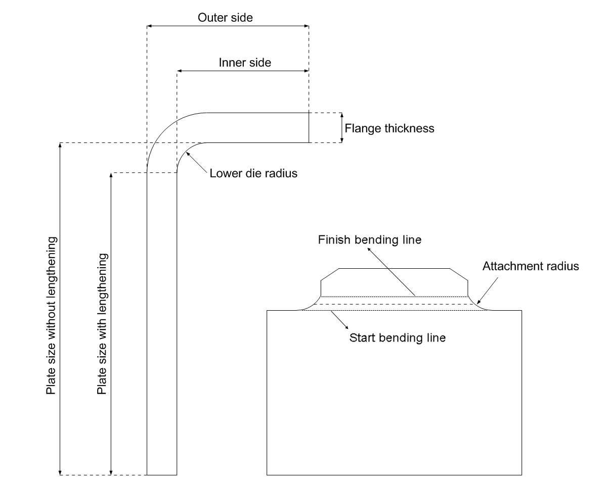
- Outer side – If Yes, the size of the flange is measured on the outer side as indicated in the figure, otherwise the inner side is used.
- Lengthening – Determines how the plate size should be determined. If Yes, the extra material in the bend is added to the flange, otherwise it is not.
- Bend line – If Yes, the line over which the flange is bend will be marked on the coded part.
Measure Body Inside Flange
Normally the body size of a flange is measured from the outer side. Enable this setting, to have the body size measured from the inner side.
Offset Bendline – Mid. Marking
Define the distance between the end of the bending line and the middle of the marking (if two marking lines are used).
This setting is applicable only if the Marking Half Breadth and Marking Height settings are both set to values larger than 0.
Marking Half Breadth
Define the half breadth of the marking.
Marking Height
Define the height of the marking.
Min. Length Bendline Two Mark.
Define the minimum length of the bending line for which two marking lines are used.
If the bending line length is shorter than this value, one marking line is used.
This setting is applicable only if the Marking Half Breadth and Marking Height settings are both set to values larger than 0.
Dimension Measured At Outer Side
Define how the flange dimension is measured.
- Client specific (default) – The dimension is measured as defined by the Radii In Contour Flange-Part setting.
- Yes – The dimension is measured at outer side
- No – The dimension is measured at inner side.
Show Bend Line At Flange
Define if the bend line is shown according to the client-specific Radii In Contour Flange-Part settings, or shown or not shown regardless of the client-specific settings.
The setting in the client-specific settings that determines whether the bend line is shown or not is the Bend Line setting (possible values Yes or No).
-
Client specific (default) – The bend line is either shown or not shown, depending on the client-specific Bend Line setting value.
In some cases two bend lines are shown, depending on the client-specific Lower Die Radius.
-
Enabled – The bend line is shown, regardless of the Bend Line setting value.
-
Disabled – The bend line is not shown, regardless of the Bend Line setting value.