Outfitting Holes
Production > Plate Cutting Data > Holes > Outfitting Holes
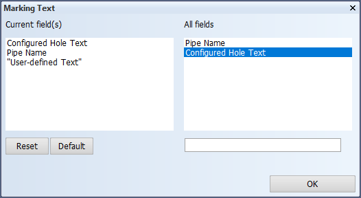
Marking Text
Configure the text for circular and oval Outfitting holes that are added to coded parts.
In the Current field(s) pane, you can add up to three parts from which the text is constructed.
-
When a hole request results from a pipe that is being routed through the hole, Pipe Name will be replaced as follows:
-
For CADMATIC Outfitting, pipe information is used. The string
<pipe name>[_<spool name>]_<outfitting user name>is replaced as follows:
Pipe name – The system name of the pipe that created the hole request.
Spool name – The name of the spool. If the spool name is not available, this part will be ignored.
Outfitting user name – The Windows account name of the user that created the hole request.
The resulting string is capped at 16 characters before added to the coded part.
-
- For PDMS Outfitting, the pipe number (passed to the construct executable when creating the hole) is used. If the pipe number is not available, an empty string will be used instead.
If the pipe information is not available, an empty string will be used instead.
-
Configured Hole Text will be replaced with a text depending on the other settings:
-
If the hole is accepted, the text defined for Accepted Hole Text will be used. See Accepted Hole Text.
-
If the hole is pending, the text defined for Pending Hole Text will be used, if Mark Pending Holes is enabled. See Pending Hole Text and Mark Pending Holes.
-
- User-defined strings can be entered in the empty field at the bottom of the dialog. User-defined strings are stored with quotation marks.
Accepted Hole Text
Define a part of the text for an accepted Outfitting hole. This text will be replaced with Configured Hole Text from the Marking Text setting when the hole is accepted.
Pending Hole Text
Define a part of the text for a pending Outfitting hole. This text will be replaced with Configured Hole Text from the Marking Text setting when the hole is pending.
Mark Pending Holes
By default, only accepted Outfitting holes are marked on the coded part. By enabling this setting, also pending holes will be marked, except pending Indication holes.
Together with the hole type and hole state, this setting affects how holes are shown on drawings and how they are added to coded parts and 3D models. This is presented in the following tables, for CADMATIC Outfitting and PDMS Outfitting respectively.
CADMATIC Outfitting holes:
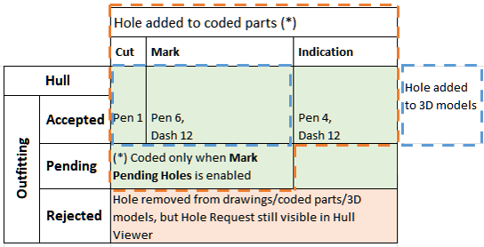
The green background indicates holes that are displayed on drawings, using the indicated pen and dash number. Holes in the area marked with a blue dashed line are included in 3D models, whereas holes in the area marked with an orange dashed line are added to coded parts. Pending holes are only coded when the Mark Pending Holes option has been enabled in System Management. Rejected holes are removed from drawings, coded parts and 3D models but they can still be viewed in Hull Viewer.
PDMS Outfitting holes:
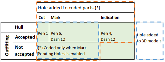
The green background indicates holes that are displayed on drawings, using the indicated pen and dash number. Holes in the area marked with a blue dashed line are included in 3D models, whereas holes in the area marked with an orange dashed line are added to coded parts. Holes that have not been accepted are only coded when the Mark Pending Holes option has been enabled in System Management.