Holes
Presentation > Holes
Define how holes are presented.
Display Marked Holes
Enabled by default. When disabled, the following applies:
- Marked holes are not displayed in the 3D model in the 3D-Show application.
- Marked holes are not displayed on plates in cross section in the 3D-Contek application. However, if a hole symbol is placed on a marked hole on a plate in cross section, the hole is always shown.
Face plates in holes are always shown.
Display Profile Holes (Bulb View)
Disabled by default. When enabled, hole symbols are shown on profiles in bulb view in the 3D-Contek application and on shell frames in shell views.
Both 3D-Contek and Shell use the holeindication.mod model for the hole symbol with pen 6. The model file is located in the mod2d subfolder of the active norms folder %ncgnorms%.
Selecting a hole symbol is activates the Construction > Holes ribbon. The hole details can be seen in 3D-Item Information. The hole can be removed with the Remove 3D-Item function, but it cannot be copied, moved or recalculated.
Alternative Hole Dimensioning
Set to Standard by default. When set to Alternative, hole dimensions can be placed to another position. Also, the dimension texts will always be either horizontal or vertical. See About Alternative Hole Dimensioning below for more information
Note: Almost all existing hole dimensions will be updated when the Alternative Hole Dimensioning setting is changed, which may lead to unexpected results. Therefore it is not advisable to change this setting in an ongoing project.
Note: When alternative hole dimensioning is active, and a hole is changed to a door hole or double-bottom hole, or a standard hole is changed to a user-defined hole, the hole dimension is removed.
About Alternative Hole Dimensioning
Alternative hole dimensioning affects the placement and orientation of the hole and corner hole dimensions in drawings.
Placement
Hole dimensions can be placed to other than the default position by dragging. For example, a hole dimension that by default is placed inside of the hole can be placed outside of the hole. The new position of the dimension outside of the hole must be such that there is enough space for the dimension arrow. If there is not enough space, the system will not accept the new position, and places the dimension inside the hole.
Presentation
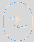
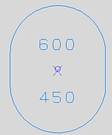
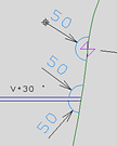
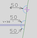
When alternative hole dimensioning is active, the angle of the dimension text is always horizontal or vertical, whereas in standard dimensioning the dimension text is either horizontal, perpendicular to the hole (corner, draining and ventilation holes), or has an angle of 45 degrees (manholes).
With rectangular holes, the dimension text is aligned with the selected edge of the hole (horizontal or vertical).
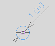
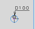
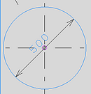
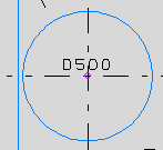
Examples
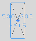
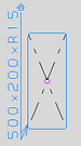
The table below compares standard and alternative hole dimensioning.
| Standard dimensioning | Alternative dimensioning |
|---|---|
|
|
|
|
|
|
|
|
|
|