Sketch Layout
Production > Profile Sketch > Sketch Layout
Edit sketch layouts for profile sketches.
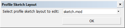
First select the profile sketch layout file to edit. The default sketch layout file is sketch.mod.
The functionality for creating and editing layouts is similar for the various sketch types (profile sketch, profile list sketch, part sketch, assembly sketch and template sketch for shell plate templates).
Sketch layouts are stored in the sketch subfolder of the project's norms folder.
First use
When this function is used for the first time, and there is no template present in the current norms, it is necessary to load a Hull model first. The Hull model will be used as a template for this function.
Next, connection points must be added to position the various types of information.
The system expects that the template is made with the normal 2D drawing system by drawings lines, text, and so on, on a specific paper size.
The template will be used for all sketches of this type. The layout of the template can be chosen freely, and it can be modified later, even if the connection points are already positioned.
There are two ways to modify the template:
- Modify the original template with the normal use of the 2D drawing system. In this case the template must be reloaded with the Get model function in the Sketch Layout dialog.
- Modify the saved template model. In this case the File > Import > Hull Model File function must used to modify the template with the normal 2D drawing system. After modifications the model must be saved with the File > Export > Hull Model File function. If you use the same template name, the sketches start using the new template immediately.
Sketch Layout dialog
Select and place the desired information on the sketch layout. The available information fields depend on the sketch type.
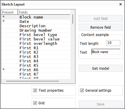
All available items are shown under Fields. An asterisk * under Present indicates that the information field already exists on the template. Use Add field to add items to the template, and Remove field to remove them.
By default, Text properties, General settings, and Grid, are visible. You can switch these selections on and off in the Sketch Layout dialog by selecting and clearing the respective check boxes.
Add field
Select a field from the list, and click Add field. An annotation text with the name of the selected field is used to indicate the position, size, rotation, length, and other attributes of the field. The text properties are directly related to the currently selected information field. You can control the position of the text by mouse movement. Left-click to place the text.
It is not possible to add the same field twice: When a field that is already present on the template is selected, the Add field is disabled.
Remove field
Select a field from the list. or select the annotation text from the model, and click Remove field. You can always add the removed field back to the model by using the Add field function.
Click Get model in the Sketch Layout dialog box to open a new template (select a Hull model file). The positioning points that are present will be resized to the new paper size of the newly loaded Hull model file. It is not necessary to use this function if the template is still correct.
Changing the position of a field
Select a field from the list, or select the annotation text from the model, and drag it using the z or Z hot key.
After selecting the information field, its position is shown in the Hint bar. The position is relative, meaning that it is related to the dimensions of the model. By entering a value in the first and/or second entry box and pressing Enter you can move a field in the model to a specific position. The third coordinate is not applicable here.
Text properties
The text properties of the selected information field can be entered in the Text properties dialog (Properties in assembly sketch layout). You cannot do this to some special fields, and therefore their text properties may be dimmed. If the field is present in the model, the new properties will apply immediately. If the field is not present in the model, the properties will be applied once the field is placed in the model.
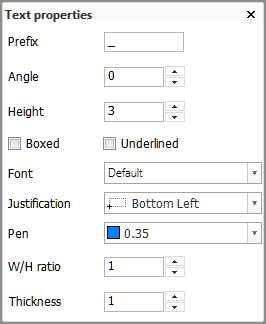
The final information on the sketch will be presented according to these properties, and will be saved together with the template. If the field defines a figure on the sketch, all properties may not be relevant. The Text length option in the Sketch Layout dialog can help to define the maximum area used in relation with the ratio and text height properties. The Text length property will not be saved: A length of 10 will be used each time the Sketch Layout function is started.
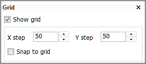
Grid
A horizontal and vertical grid can be used to make it easier to align fields exactly. You can set the (relative) step size. If Snap to grid is selected, new fields and existing fields that are moved will snap to the nearest grid point.
General settings
General settings are available for profile sketches and profile list sketches only.
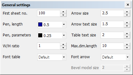
The following values can be specified in the General settings dialog:
-
First sheet no. – The number of the first sheet.
-
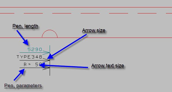
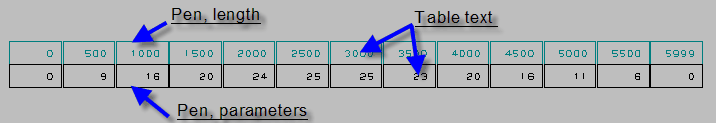
Pen, length – Define the pen number of the dimensions that indicate the position of the cutout or marking on the profile.
-
Pen, parameters – Define the pen number of the dimensions that indicate the parameters of the cutout or marking on the profile.
-
W/H ratio – Set the width-height ratio of the sketch.
-
Font table – Select the font.
-
Arrow size – Define the size of the arrow of the dimensions that indicate the parameters of the cutout or marking on the profile.
-
Arrow text size – Define the size of the text of the dimensions that indicate the parameters of the cutout or marking on the profile.
-
Table text size – In case a bending table of the Create Production Information function (for shell frame profiles) is requested in the Sketch Layout dialog, the size of the bending table depends on this setting.
-
Max.dim.length – Define a length to avoid the dimensions overlapping each other in case the distance between them is too short. The value is the amount of characters drawn to avoid overlapping.
-
Font arrow – Set the font used to draw an arrow.
-
Bevel model size – Set the enlargement factor for bevel models and the variable bevel angle marker model on a profile sketch. The default value is 2. It is assumed that the model is created for scale 1:25.
Note: This setting can only be changed for profile list skecth, not for profile list sketch.
Additional information
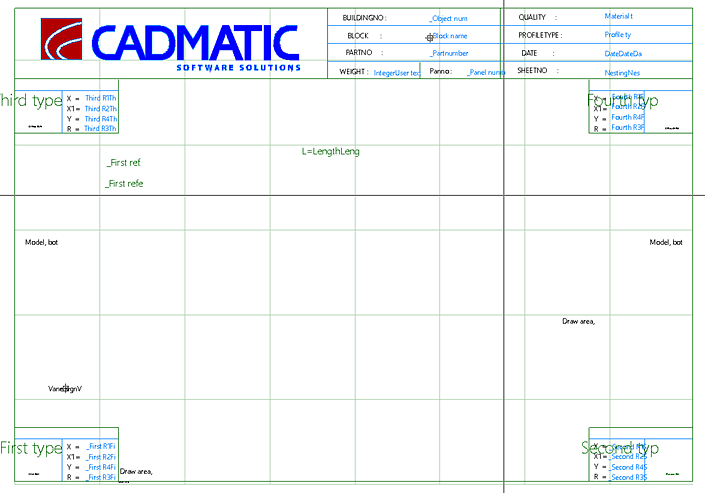
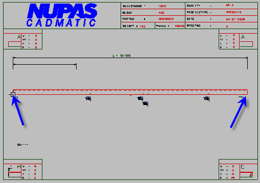
Position of the main drawing – The fields specifying the position of the profile sketch (Model, bottom left and Model, bottom right) must be present in the sketch. It is not possible to save the profile sketch if these fields do not exist.
Because the positions of the fields in the model and the model itself are regarded as two separate entities, it is possible to use Get model to select a different model to which the current field positions will apply.
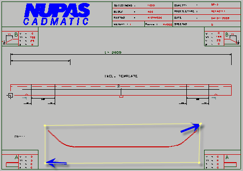
Bending table/face plate – Specify the Draw area, bottom left and Draw area, bottom right fields to define the location of a bending table or face plate in side view.
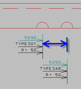
Reference lines – Two reference line markings with text can be added to profile sketches. A reference line marking consists of a dimension line and a text.
You must add the following keywords to the robot layout file ncgrobot.ind for the reference lines to show in the profile sketch:
FIRST_REF_LINE_LENGTH
FIRST_REF_LINE_TEXT
SECOND_REF_LINE_LENGTH
SECOND_REF_LINE_TEXT
I,C,$FIRST_REF_LINE_LENGTH,3;NC-PARAMETERS> 902,1,0,0,0,0,0,0,$LIJFHOOGTE,1,0,0,0,$LIJFHOOGTE,0,0,0,0,0,0,0,0,0,0,0,0
I,C,$FIRST_REF_LINE_LENGTH,2;NC-PARAMETERS> 506,$FIRST_REF_LINE_LENGTH,20,$FIRST_REF_LINE_LENGTH,$LIJFHOOGTE,40,$FIRST_REF_LINE_TEXT
I,C,$SECOND_REF_LINE_LENGTH,3;NC-PARAMETERS> 902,1,0,0,0,0,0,0,$LIJFHOOGTE,1,0,0,0,$LIJFHOOGTE,0,0,0,0,0,0,0,0,0,0,0,0
I,C,$SECOND_REF_LINE_LENGTH,2;NC-PARAMETERS> 506,$SECOND_REF_LINE_LENGTH,20,$SECOND_REF_LINE_LENGTH,$LIJFHOOGTE,40,$SECOND_REF_LINE_TEXT
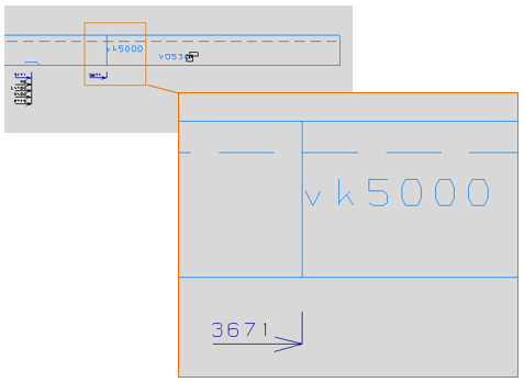
The position and the line and text (VK 5000 in the example below), are controlled by the following information fields:
- First ref. line length (line) and First reference line (text) on the left side
- Second ref. line length (line) and Second reference line (text) on the right side
The dimension line can be part of the layout template as shown in the example below. In this case the dimension is always present, and has a fixed length related to the layout template. The information fields will be only filled in if contents are given by the system.
In some cases the reference dimension does not need to have a fixed position, and needs to be always present. In that case two or four of the following fields must be defined: Left ref. line, start, Left ref. line, end, Right ref. line, start and Right ref. line, end. If these fields are defined, the reference lines will be drawn with their actual length. There is one exception: If the position of the Left ref. line, start, Left ref. line, end is smaller than the reference length, the dimension will be drawn to the end position defined by the Left ref. line, end point. The same rule applies to the right side.
Details on sketch – It is possible to position some details on the sketch layout, such as cutouts and profile end types. See Details on sketch in the Norms Type Files Administrator's Guide for more information.
Conversion – If the system detects a profile sketch that was created before version 4.4, the sketch is converted to the current version and saved automatically when the Sketch Layout function is started. The profile sketch will also be converted from the older version when the Create Production Information function in the 3D-Contek application is used with the Sketches option selected.