Plate deformation compensation
When a part such as face plate is welded on a plate, the plate may shrink at the weld side. By applying deformation compensation to the weld side of the plate you can compensate for the shortening of the plate. The compensation adds extra length to one side of the plate. This extra length will then be neutralized in welding.
A plate can have more than one deformation compensations, but the deformation lines must not intersect. The deformation line goes from the deformation start point to the end point, thus intersecting the plate contour twice.
- Applying deformation compensation
- Modifying deformation compensation
- Copying and moving deformation compensation
- Deformation compensation when plate is modified
- Deformation compensation in the coded part
Applying deformation compensation
Deformation compensation is applied to two sides (relations) of the plate (a value of zero can be defined for either side). You select the first side relation, and another relation will be the other side where the deformation compensation is applied. This other relation depends on the angle from the rotation point, which is on the first relation.
Do the following:
-
Select Construction > Welds > Compensation > Deformation in the 3D-Contek application.
-
In plan view, indicate the first relation (side) of the plate where deformation compensation will be applied (start compensation). Only plates in a solid (not dashed) block can be selected.
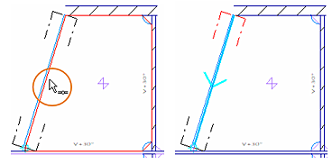
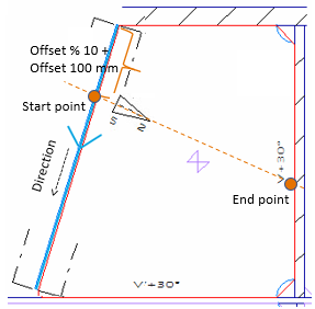
The system highlights the selected plate, and indicates the selected side of the plate with a line using pen 5 with thickness 2. An arrow indicates in which direction the deformation is applied on the plate.
The Create Deformation Compensation dialog opens:
-
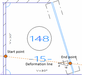
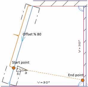
Enter the percentage of offset in Offset (%), and/or absolute offset value in Offset. The offset determines the point where the start compensation is applied. For example, if the length of the side of the plate is 1200, an offset percentage of 50 and an absolute offset of 100 mm will result in an offset of 700 mm (600+100). The start point is also the rotation point for the angle.
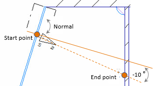
The end point is at the opposite relation, at the intersection of the line drawn from the start point at the given angle to the normal of the first relation.
 Show/hide image
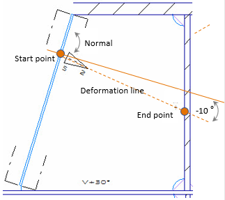
A negative angle of 10 degrees used (350 degrees).
-
Optionally, enter the Angle. If the angle is not entered, it will be perpendicular to the relation.
This angle is defined as an angle to the normal of the first relation. The start point on the first relation is the rotation point of the angle. The angle determines where the end point is.
-
Enter the extra length in mm to apply at the start point and at the end point of the deformation compensation in Start compensation and End compensation, respectively. If the start and end relations are parallel, and the deformation values are the same, the shape of the plate will not change. Otherwise the shape of the plate will change.
- The values must not contain more than two decimals.
- Negative values are not accepted.
- If a compensation value is not entered, it is considered to be 0 (zero).
-
Click OK.
Presentation of deformation compensation
Deformation compensation is presented in the view as the deformation symbol at the side of the plate.
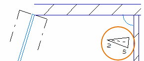
The numbers are the start and end compensation values (5 and 2 respectively).
The deformation line symbol is a user-defined model, deformation.mod, which can be modified as desired.
In the two examples below, the plate is highlighted in red, and the first relation is highlighted in blue.
| Example 1 | |
|---|---|
|
|
| Example 2 | |
|---|---|
|
|
Modifying deformation compensation
Do the following:
-
Select Construction > Welds > Modify > Deformation Compensation in the 3D-Contek application. The Select item dialog opens.
-
Select the deformation compensation(s) to modify.
-
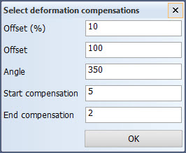
Click OK. The Select deformation compensations opens:
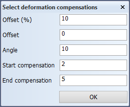
The current values are shown in the dialog. If the selected deformation compensations have different values, the corresponding fields in the dialog show up as empty.
-
Change the Offset (%), Offset, Angle, and Start compensation and End compensation as desired. For more detailed information on the these values, see steps 3-5 in Applying deformation compensation above.
-
Click OK to apply the changes.
Copying and moving deformation compensation
The deformation compensation attribute can be moved and copied with the General > Copy 3D-Items and General > Move-3D Items functions, similar to moving and copying shrinkage compensation and extra length attributes.
When a plate with deformation compensation is moved or copied, the deformation compensation attribute is moved or copied with the plate.
In case a deformation compensation cannot be placed, the system displays an error message.
Tip: When a face plate is welded on a long girder, the girder plate sometimes gets several small deformations along its contour, making the plate slightly curved. In such a case deformation compensation is needed at several points on the plate contour. In these cases it is advisable to create just one deformation compensation attribute, and copy it to where it is needed.
Deformation compensation when plate is modified
When a plate that has deformation compensation is modified or recalculated, the deformation compensation attributes are also recalculated.
If a plate that has deformation compensation is split, and the starting and end points of the deformation compensation end up on the same plate, the deformation compensation is kept. If the starting and end points would end up on different plates, the deformation compensation is removed.
If a plate that has deformation compensation is joined with another plate, the system recalculates the offset so that the starting point of the deformation remains at the same position.
Deformation compensation in the coded part
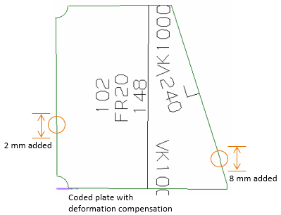
The contour of the plate is extended at the start point and the end point of the deformation compensation, by the amount defined as the Start compensation and End compensation, respectively (a value of zero can be defined for either).
In the example below, the start compensation is 2 mm and the end compensation is 8 mm. Because the values are different, the shape of plate is slightly deformed.