Templates wizard: create templates for plates
Using the Templates Wizard you can create custom templates for shell plates. The Templates Wizard consists of the four tabs of the Create templates for plate dialog. as follows:
In the Planes tab you define the settings for the sight plane(s), the sight line plane, and the offsets for the Aft and Forward templates.
When the Templates contour perpendicular to sight plane option is selected, the templates relate with 90 degrees to the sight plane.
Note: To ensure that all dimensions in the template sketch are presented correctly, select this option. If this option is not selected, some of the dimensions in the template sketch may be presented incorrectly.
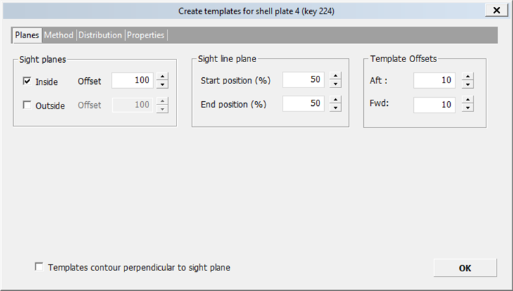
Sight plane(s)
A template set can have one or two sight plane(s). A sight plane for a shell plate(s) is positioned either in the direction inside or outside of the ship. The offset is the distance from the default sight plane position. The default position of the sight plane(s) is on the two of the sides/faces of the tight bounding box of the shell plate(s). One in the inside direction, and the other one in the outside direction.
Inside:

Outside:

Sight line plane
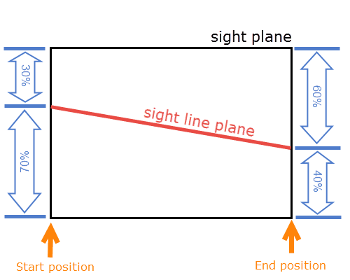
The sight line plane is defined using the sight plane and the Start position (%) and End position (%) settings.
For example, with a start position of 70%, and end position of 40%:
Template offsets
This is used to specify an offset from the edge of the shell plate for the Aft and Forward templates only. The offsets are used to place the Aft and Forward templates within the edges of the shell plate. The default offset value is 2 * Plate Thickness (as indicated by the Template Thickness setting in System Management). The offset is a positive value (>=0) and there is no maximum limit defined for this value.
In the Method tab you select the method and set the angles in which the templates should be positioned. The three methods available are On grid, Angle to sight line plane and sight plane, and Angle to sight line plane and shell plate.
When the Templates contour perpendicular to sight plane option is selected, the templates relate with 90 degrees to the sight plane.
Note: To ensure that all dimensions in the template sketch are presented correctly, select this option. If this option is not selected, some of the dimensions in the template sketch may be presented incorrectly.
Method and Angles
The available Angles settings depend on the selected Method.
On Grid
Templates are positioned along the grid coordinates, that is, length/frame, width, height. When the templates wizard is opened for the first time the default grid dimension is calculated based on the position and shape of the shell plate (for example, along the length if length is the max of length, width, and height).
Example: Templates on the frame
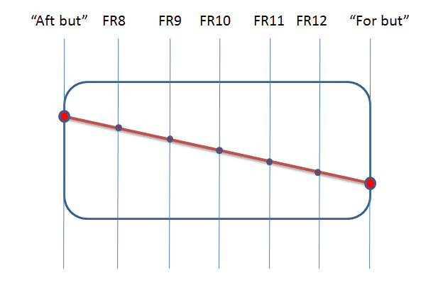
All angle options are disabled for this when On grid is selected. The angle of the sight line plane plate to the sight plane is always presented as 90 degrees at the top of the template in the template plate drawing.
Angle to sight line plane and sight plane
With this method it is possible to modify the plane of all templates with a fixed angle to the sight line plane, and a fixed angle to the sight plane. The picture below illustrates how templates are positioned when this option is selected.
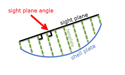
Angle options Angle to sight line plane and Angle to sight plane can be defined.
Angle to sight line plane and shell plate
With this method it is possible to modify the plane of all templates with a fixed angle to the sight line plane, and a fixed angle to the shell plate. The picture below illustrates how templates are positioned when this option is selected.
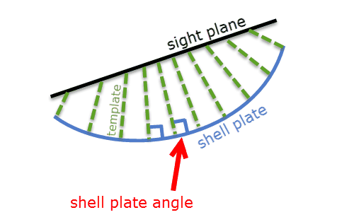
Angle options Angle to sight line plane and Angle to shell plate can be defined.
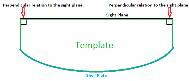
Template contour types
The two possible types are:
-
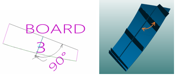
Perpendicular relation to the sight plane. This relation is used when the Templates contour perpendicular to sight plane option is selected. The template is created using a 90 degrees relationship with the sight plane.
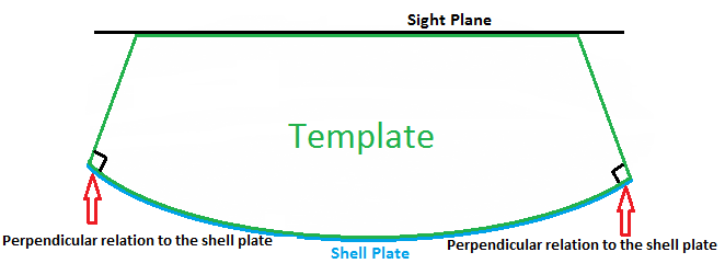
-
Perpendicular relation to the shell plate. This relation is used when the Templates contour perpendicular to sight plane option is NOT selected. The template is created using a 90 degrees relationship with the shell plate.
In the Distribution tab you set the exact position of the templates.
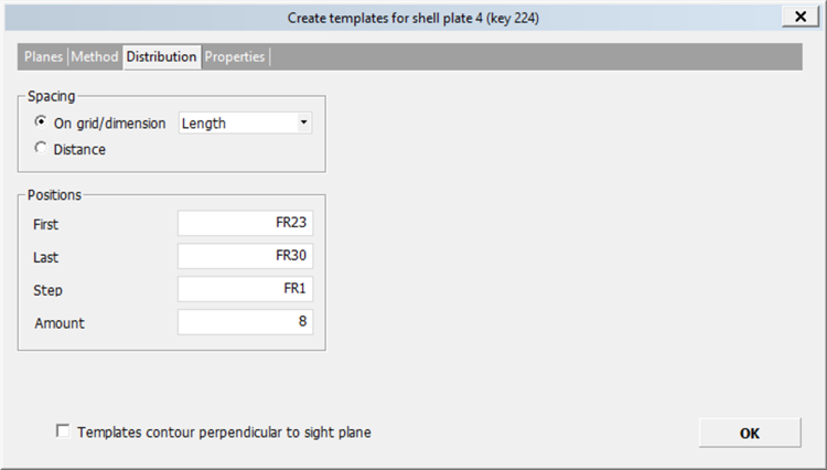
Spacing
Templates can be distributed using either a grid/dimension or by giving a distance.
Positions
Note: There will always be templates on the start and end point of the sight line unless the user has removed them.
- First – The first template position on the start point of the sight line.
- Last – The last template position on the end point of the sight line.
- Step – The step size used for positioning the middle templates.
- Amount – The number of templates.
When the Templates contour perpendicular to sight plane option is selected, the templates relate with 90 degrees to the sight plane.
Note: To ensure that all dimensions in the template sketch are presented correctly, select this option. If this option is not selected, some of the dimensions in the template sketch may be presented incorrectly.
The Properties tab consists of three panes listing the templates in the template set with their angles.
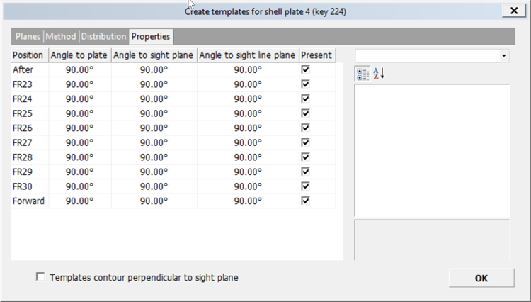
When a template is selected, the angles of that template are shown on the right side of the dialog.
- Angles of the selected template can be modified by clicking in the value fields. The angles which can be modified depend on the positioning method that is used.
- A short description of the selected angle type is displayed at the bottom right.
When the Templates contour perpendicular to sight plane option is selected, the templates relate with 90 degrees to the sight plane.
Note: To ensure that all dimensions in the template sketch are presented correctly, select this option. If this option is not selected, some of the dimensions in the template sketch may be presented incorrectly.