Work Breakdown 2D Drawing
The Work BreakDown 2D Drawing function in the 3D-Contek application generates assembly drawings according to the work breakdown structure. The function generates several drawings for each work breakdown level. Also WBD 2D sketches can be created.
The system creates a drawing for each plate, bracket, shell frame and face plate within the work breakdown tree. Face plates in holes are not handled however.
The system considers lugs so that if a plate, profile or shell frame has a cutout which has a lug, a drawing showing the lug will be created, even if the drawing would only contain lugs. This way, all lugs in the assembly will be shown in a WBD 2D drawing.
Generating WBD 2D drawings and sketches
Select Production > Production > WBD 2D in the 3D-Contek application. The Work BreakDown 2D Drawing dialog opens
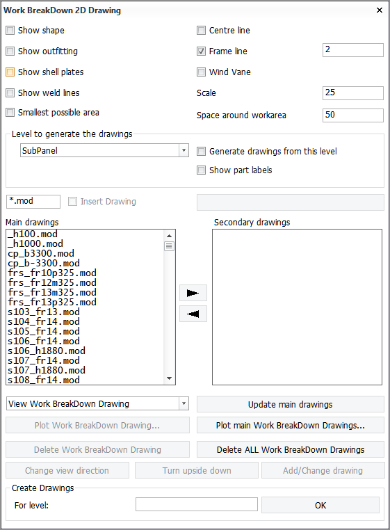
The Main Drawings and Secondary Drawings panels list previously generated drawings in the selected WBD level. You can move parts from one list to the other by using the arrow buttons  and
and  .
.
Do the following:
-
Select what to include in the drawings:
-
Show shape – Show the hull shape.
-
Show outfitting – Show outfitting parts, such as pipes and equipment.
-
Show shell plates – Show shell plates.
-
Show weld lines – Show weld lines. Only those weld lines that belong to the same work breakdown level are shown.
-
Smallest Possible Area – When selected, only the specific part and no surrounding construction items are shown.
Note: The Space around workarea setting has no effect when this option is selected.
-
Centre line – Show the centre line. The centre line can only been seen in top views and certain slanted views.
-
Frame line – Show frame lines. Frame lines are added according to the default length grid of the block. The value defines the step for showing frame numbering. For example, with the value of 1 all frame numbers are shown, and with the value of 2 only even frame numbers are shown.
-
Wind Vane – Show the wind vane.
-
-
Set the Scale of the drawings, and specify the Space around workarea. This is the size of the area around the part to be included in the drawing. Nearby construction falling within this area will be included in the drawings.
-
In Level to generate the drawings, define the WBD level from which to generate drawings and perpendicular views. Only parts in the selected level will be used when generating the drawings and views. The options are Block, Panel, and SubPanel.
By default drawings are generated only from the selected level, and not from the lower levels. Select Generate drawings from this level to generate drawings also from the lower levels.
If you want to use part labels instead of WBD branch name labels, select Show part labels. Part labels – and only part labels – are then shown in the drawings for this level and the levels below it. Each drawing will contain all part labels from that level and also from the lower levels. WBD branch name labels will be used in the drawings for higher levels than the level selected in Level to generate the drawings. Note that the lowest level always shows part labels.
-
If you want to insert drawings from both the main and secondary drawing lists, select Insert Drawing. A dialog opens where you can either save the drawing or cancel the operation.
-
View Work BreakDown Drawing / View Work BreakDown Sketch drop-down menu – Select whether to generate drawings or sketches.
-
Enter the name of the WBD tree for which you want to generate the drawings. All drawings for this WBD tree will be (re)created. If no WBD tree name is entered, drawings will be created for all the WBD trees in the WBD level specified in Level to generate the drawings.
-
Click OK to generate the drawings or sketches. The system recalculates the perpendicular views.
The drawings are shown in the graphical window one by one while the system generates them. Once all the drawings are generated, you can view any of them by selecting the drawing from the list. The drawings will be presented in the same list in which they appeared previously. However, drawings which no longer exist will be removed, and new drawings will be listed in the main drawings list.
Additional functions
The following functions are available for the generated drawings:
-
Update main drawings – Update all the drawings listed in Main drawings. The drawings in Secondary drawings are not updated.
-
Plot Work BreakDown Drawing – Plot the drawing that is currently displayed in the graphical window.
-
Plot main Work BreakDown Drawings – Plot all the drawings that are listed in Main drawings.
-
Delete Work BreakDown Drawing – Delete the drawing currently displayed in the graphical window.
-
Delete ALL Work BreakDown Drawings – Delete all the drawings in both lists.
-
Change view direction – Change the view direction of the drawing currently in the graphical window.
-
Turn upside down – Rotate the drawing currently in the graphical window by 180°.
-
Add/Change drawing – If the drawing is changed, the main dialog is closed and a new dialog opened. A dialog opens where you can either save the drawing or cancel the saving.
Note: Another function can be started while the Work BreakDown 2D Drawing dialog is open. If another function is started, the Work BreakDown 2D Drawing function will stop until the drawing is saved, and then the main dialog of the Work BreakDown 2D Drawing function will be displayed again.