Work Breakdown 3D Sketch

With the Work Breakdown 3D Sketch function you can generate assembly drawings according to the work breakdown structure.

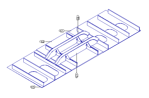
The sketch shows a 3D view of the selected construction. By default there are part labels indicating the assembly order. The items can also be presented in a table.

Generated sketches can be previewed in the graphical window and printed/plotted, and also loaded into a sheet drawing.

Setting up WBD 3D sketches

Define in the assembly sketch layout what information should be presented in the sketch and how it should be positioned, System Management > Production > Assembly Sketch > Sketch Layout.

The appearance of the items in the sketch can be defined with the various settings under System Management > Production > Assembly Sketch > Settings. Here you can define the table properties, label properties, drawing properties, and also settings for the center of gravity (COG) markings and reference points, and some saving settings.

To include a table presenting the construction items in the sketches, a report layout must be defined for each WBD level. See Levels for details on creating the report layouts for WBD 3D sketches.

Generating WBD 3D sketches

Select Production > Production > WBD 3D in the 3D-Contek application. The Work BreakDown Sketch dialog opens.

First you select the parts for the sketch(es), then the level in the WBD tree from which you want the sketches generated and also up to which branch. You have options for the naming of the sketches, and the view direction and scaling used in the sketches. Once you have made all your selections, click OK the generate the sketches.

Note: The part list in the WBD 3D sketch includes only the parts in the sketch. The system does not count the parts inside a level, only the loose parts.

Selecting the parts

Part selection for sketches can be done by report, or the parts can be selected in Hull Viewer.

The previous part selection is shown at the top of the dialog. The number of selected plates and profiles are shown, together with an overview of these parts. The date and time indicate when this selection was made. If the selection is out-of-date, make a new selection.

Do the following:

In Selection criterion, select the report by which you want the parts selected, or select Hull Viewer to open Hull Viewer for part selection.

  • When parts are selected by report, the system creates a sketch for each branch in the work breakdown tree.

  • When parts are selected in Hull Viewerr, the system creates for each branch one sketch that includes all the selected parts.

    Note: To get proper part labeling for all the WBD levels, select Block in Level to generate the sketches, and Part in Level info on sketch. Otherwise there may be empty or missing part labels in the subpanel sketches.

  • If Create sketches, in Steps of is defined, the sketch will be split into several sketches, each representing a production step. The number defines how many part labels a single sketch has, and thus affects the number of sketches is generated. Each production step sketch will get extension _s[number] in the sketch name, the number indicating the assembly order.

    Tip: You can distinguish between the current and the previous production steps in the sub-sketches by defining different pen numbers for Drawing Pen and Previous Drawing Pen in System Management > Production > Assembly Sketch > Settings > Drawing Properties.

The sketches resulting from your selections are listed under Sketches. The Missing items on Sketch list shows those part numbers that are missing from the sketch. These parts could be either too small to include in the sketch or they are behind other parts, and cannot be presented in the sketch.

Selecting the WBD level

In Level to generate sketches, select the WBD level from which to generate the sketches. By default sketches are generated only from this level, and not from the lower levels. Select Create up to and incl. branch to generate sketches also from the lower levels and branches.

You can also select the work breakdown branch where labeling starts in Level info on sketch (Panel, SubPanel, Part, or any WBD level created by the system manager).

Part labels

Part labels are included in the sketches by default. If you want to generate the sketches without part labels, select No labels.

Once the sketches have been generated, part labels can be moved to different positions within the sketch.

Do the following:

  1. Select the desired sketch.

  2. Click Add/Change drawing.

  3. Select Draw > Symbols > Labeling or Production > Logistics > Labeling.

  4. Do one of the following, depending on how you want the lead line to behave:

    • To move a label so that the label's lead line keeps its length and orientation, click on the label that you want to reposition. This way the label can be repositioned so that the lead line points to the middle of the part instead of the part contour, for example.

    • To reposition a label so that a new lead line pointing to the part contour is created for it, click the part whose label you want to reposition.

  5. Drag the label to the desired position, and click on that position to place the label.

  6. Repeat steps 4 and 5 for as many labels as desired.

  7. Click Save drawing to save the changes, or select Cancel to cancel the changes.

Part labels can also be added manually in case there are no part labels in the skecth, or if labels are missing for parts.

Do the following:

  1. Select the desired sketch.

  2. Click Add/Change drawing.

  3. Select Draw > Symbols > Labeling or Production > Logistics > Labeling.

  4. Select the part for which you want to add a label. The label appears.

  5. Drag the label to the desired position click to place it.

  6. Repeat steps 4 and 5 for as many labels as desired.

  7. Click Save drawing to save the changes, or select Cancel to cancel the changes.

Showing weld lines

It is possible to show weld lines in the WBD 3D sketch. Weld lines can be labeled by using the standard weld label.

Weld information is shown in a weld table which is placed between the part list table and the reference points table. The table lists all weld lines with the same weld type (keyword WTY), weld method (WMT), weld height (WTH) and weld length (WTL) on the same line, with the length and weight totals for each weld type-method-height-length combination. Note that the keywords must be included in the calclweldinfo.cmd macro for them to appear in the table (see the Note below). Only the weld data for which keywords are included in calclweldinfo.cmd is presented in the weld table.

In Weld presentation, select which weld lines to include in the sketches and the weld table:

  • None – Weld lines are not shown in the sketches and there will be no weld table.

  • Based on Manager – Weld lines are shown based on where the welds are located in the Weld Manager tree.

  • In branch – Weld lines for the parts in the WBD branch selected in Level to generate the branch data are shown. Weld lines for parts that belong to lower WBD branches are not shown.

  • All weld lines – Weld lines for the parts in the selected WBD branch and the parts that belong to its sub-branches are shown.

Note: The Create Weld Lines Models setting in System Management > Construction > Welds/Bevels > Settings must be enabled to show weld lines.
Also, a user-defined macro, calcweldinfo.cmd, must be present in the weld folder of the project norms in (<project>\norms\cvar\weld). No weld data is available without the macro. See calclweldinfo.cmd for more information and an example.

The pen number and thickness of the weld lines can be set with the Weld Line Pen and Weld Line Thickness settings, respectively, in System Management > Production > Assembly Sketch > Settings > Drawing Properties.

Reference points

Reference points are shown in the WBD 3D sketch. The first 10 points in the reference points list are also shown in a table in the WBD sketch. The reference point table is positioned above the part table and the weld table. If there are no reference points defined, the table will not be added.

It is possible to have extra space added to the cells for manual user input by enabling the Reference Point Table Extra Space setting in System Management > Production > Assembly Sketch > Settings > Table Properties.

Table properties.

Several properties can be defined for the appearance of the tables in Work BreakDown 3D sketches in System Management > Production > Assembly Sketch > Settings > Table Properties.

Sketch names

Sketch names have a fixed structure consisting of parts that are separated by underscores. An optional Sketch extension part can be defined to make the sketch names more unique.

  • Sketch name incl WBD levels – When selected, the work breakdown level name contains the entire name including all levels up to the block level, separated with '_' (underscore).

  • Sketch extension – The string defined here will be added to the sketch name after the WBD level name.

  • Create sketches, in Steps of – When defined, the sketch will be split into several sketches, each representing a production step. The number defines how many part labels a single sketch has, and thus affects the number of sketches is generated. Each production step sketch will get extension _s[number] in the sketch name, the number indicating the assembly order.

    Example: 109_subpanel_mysketch_s01

    Tip: You can distinguish between the current and the previous production steps in the sub-sketches by defining different pen numbers for Drawing Pen and Previous Drawing Pen in System Management > Production > Assembly Sketch > Settings > Drawing Properties.

View direction and scale

The system uses the orientation of the first part in the WBD level as the viewing direction for the sketch of that branch when part selection is done by report. If you select Fix View Direction, the viewing direction used for the first sketch will be used for all sketches. This way, the viewing direction will be the same in all sketches. This can be helpful to make an assembly composition.

If the parts are selected in Hull Viewer, the orientation of the first selected part is used as the viewing direction for all parts in the sketch.

In Scale you can define the scale used for the sketch(es), relative to the sketch layout size.

Model at small view

The sketch layout can have two viewing areas. By selecting the Model at small view option the 3D model will be positioned in the so-called small area. Then you can, for example, add a 2D view next to the 3D sketch by using the Load WBD function in the sheet drawing environment.

Rotating items in the sketch

The Rotate function splits the view into two windows. The models in the sketch can be rotated in different ways in the right side window using rotation tools.

xrot, yrot, and zrot rotate the view along the x, y, or z axis with the given Angle.

Missing items highlights the parts that were not visible before the rotation. This function is only available if there are parts in the Missing items on Sketch list.

Click Save to save the rotated view. The drawing will be repositioned in the sketch, and the labels will be re-generated.

Note: To save the sketch with a different name than the original unrotated sketch, enter a string in the Sketch extension field. Otherwise the rotated sketch will be overwritten.

Click Cancel in the main dialog to restore the view to the previous situation.

Rotating items after selected WBD branch

Items in Work BreakDown 3D sketches can be rotated after a selected Work BreakDown branch. The rotation can be done around the X, Y or Z axis, and the amount of rotation can be set freely. The rotation is done relative to the first part in the selected WBD branch.

Define the following:

  • Create sketches, in Steps of – This option must be set to 1.

  • Rotation (Y180) – Enter the amount of rotation in degrees. If the axis (X,Y,Z) is not defined, the system assumes Y axis.

  • Rotate – Enter the amount of additional rotation in degrees with which the first rotation is amended. If the axis (X,Y,Z) is not defined, the system assumes Y axis.

  • after item name – Enter the name of the step in the WBD tree below which the rotation should be applied in the sketches. Part numbers are not accepted. All sketches for the WBD steps after the entered WBD step are rotated. Note that the sketches for the subsequent steps must exist already when rotation is applied.

Center of gravity markings

The center of gravity (COG) point at the Work BreakDown level (subpanel, for example) can be shown in WBD 3D sketches. The COG point is shown if the text for indicating it is defined. This can be done in System Management > Production > Assembly Sketch > Settings > COG Text, Text At COG Point setting.

If Create sketches, in steps of is defined, the sketch will be split into several sketches, each representing a production step. The number defines how many part labels a single sketch has, and thus affects the number of sketches is generated. Each production step sketch will get extension _s[number] in the sketch name, the number indicating the assembly order. In this case each sub-sketch shows the COG point of the part that is being added at that step, not the point of the total COG of the WBD level.

Note that COG is only shown for individual steps if all parts in the WBD branch are solid parts. If not, the total COG of the WBD level is shown in the sub-sketches as well.

The COG in the table at the top of the sketch always shows the total COG of the WBD level.

Deleting sketches

To delete one or more sketches, select the sketch(es) in the Sketches list, and then click Delete WBD sketch.

To Delete all the sketches in the list , select Delete ALL Work Breakdown sketches, and click Yes in the confirmation dialog.

Adding, changing and saving drawings

You can modify the drawing part of the sketch by using the functions in the Draw ribbon. For example, you can add shapes and dimensions, and add and reposition Part labels.

Select a sketch in the Sketches list, click Add/Change drawing, and make the desires changes.

Click Save drawing to save the changes, or click Cancel to cancel the changes.

Updating sketches

Select a sketch in the Sketches list to update it to reflect the currently made changes.

Note that any unnecessary sub-sketches must be removed manually.

Previewing sketches

You can preview the sketch output in the graphical window. Make sure View Work Breakdown sketch is active, and then select a sketch in the Sketches list.

Printing/plotting

You can print/plot WBD sketches with the following functions:

  • Plot Work BreakDown sketch – Print/plot the selected sketch.
  • Plot all Work BreakDown sketches – Print/plot all sketches.