Automatic PDF generation
Hull Viewer can automatically generate a PDF containing images of building stages according to the Work Breakdown Structure.
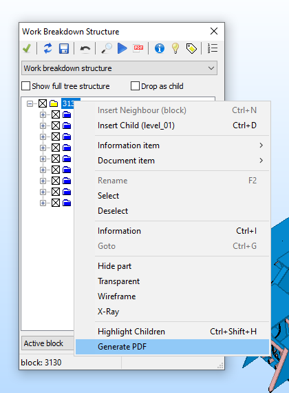
Right-click on an item from the active block in the tree view to show a menu and select Generate PDF. Or Shift-click the Create PDF icon  in the toolbar.
Note: The Generate PDF function is available only when the view is set to the default WBD hierarchy, the block level (of the active block) is selected, and the configuration file (norms/lvar/autopdf.cfg) is present.
General layout
Each branch in the WBD structure of a block produces a series of images that show the building process by adding parts in each new image. Previously added parts are grey and added parts have their usual Hull Viewer color. The level at which the steps are taken and rules for which parts to include can be configured. The levels and rules can be set for smaller and larger steps in the same PDF.
For information on the configuration settings, see Automatic PDF generation configuration file.
Note: Make sure that all involved parts are visible in Hull Viewer. The PDF generation function will not load them.
The PDF starts with one or more overview pages containing smaller versions of the images of the steps. After the overview pages, the full-sized images follow, each on a separate page.
The preview images are presented in a table-like layout with a custom number of rows and columns. Each image, whether in the overview or the regular-sized images, can have a title and a caption. The caption in the overview is only displayed for the first image of a series. For the regular-sized images, the caption is present on each page.
Here is an example of an overview page:

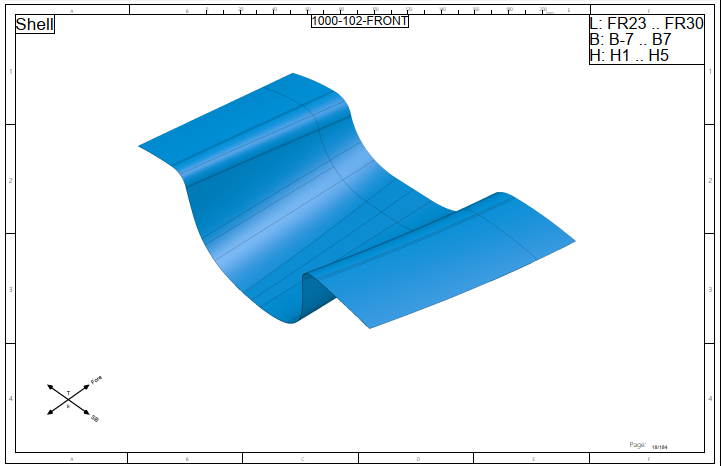
All images include a vane indicating the orientation of the parts. Only the most relevant axes are named in the vane. For the other directions, only the abbreviated axis name is displayed.
The orientation of the images can be manually set by inserting information items with a specific view at the first sub-level below the level that is being processed. If no such information item is present, an attempt is made at calculating a suitable view.
You can define 1-3 layouts for the pages in the PDF: one for the first page, one for the other overview pages, and one for regular pages which contain the regular-sized images. The layouts are defined as model (.mod) files. These models can contain keywords, such as blockname and currentdate, inside % marks which are then resolved during transfer to the document.
The system figures out where there is space within the provided template to position the images. For example, if there is a table or title field that prohibits the image placement in certain part of the page, such as the title field in the lower right corner in the image above.
Box texts and values
To present the location of the parts in the image, the (rounded) box values can be placed on the page. When using rounded values, the minimum values are rounded up to the next whole grid number or multiple of 100 mm. The maximum values are rounded to the previous whole grid number or multiple of 100 mm.
The default grid values are used for width and height by default. But with the boxtype setting, you can prevent rounding and/or use millimeter values instead of default grids.
The placement of titles, captions and box values is controlled by settings for position and size. Position is limited to 9 positions, ranging from top-left to bottom-right. Box texts and their rounding is optional.
You can set the box values in two different ways:
-
Use the settings %boxpos% and %boxtxts%.
-
Set prefixed length/width/height values. The model for the regular pages can contain the texts %boxminl%, %boxminb%, %boxminh%, %boxmaxl%, %boxmaxb% and %boxmaxh%. These keywords are then replaced by the corresponding box values.
For more information on the configuration settings, see Automatic PDF generation configuration file.