Clipping
To enable clipping, select View > Clipping, or the view cube toolbar icon  . Select Enable clipping.
By using clipping you can show only a specified area of the model. The area outside of the specified area is clipped, that is, not shown the view.
You can disable or enable each of the six clipping planes, and enter the minimum and maximum boundaries for the area to be shown in length, width and height. Length units (mm/inch) and grid values can be used.
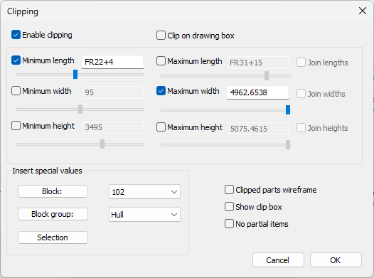
Note: Using a width grid whose direction is towards the port side is not reflected in the presentation of the breadth (width) values here. The system always shows the minimum (port side) values as negative and the maximum (starboard) values as positive. Positive minimum values and negative maximum values can be entered in the input boxes for breadth if the width grid runs towards the port side, but when the settings are opened again, the minimum values are shown as negative, and maximum values as positive.
The view in the 3D-Contek application (the drawing box) can also be used to specify the clipping planes. This is done by selecting the Clip on drawing box option. When selected, only the area of the 3D-Contek view is displayed, and the rest is clipped. You can also leave out parts that are not completely within the clipped area by selecting No partial items.
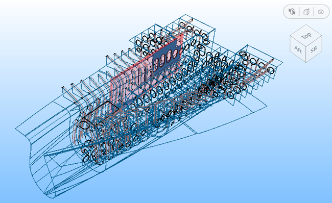
It is also possible to view the clipped part within a wireframe model of the view by selecting Clipped parts wireframe.
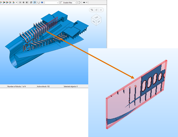
The block area or block group can be inserted by clicking Block or Block group. The area of the selected block or block group will be inserted in the edit fields in the dialog.