Extra length in profile sketches
By default the total profile length in profile sketches includes the length added to the profile end types as extra length by using the Green function. The system takes the profile length + extra length value from the $BASIS variable in the robot layout file for profile sketches (ncgrobot.ind by default) when generating the sketches. $BASIS is the profile length including the extra length.
Instead of the default behavior, it is possible to make the system use the extra length defined in the type file of the profile end type. This can be done by changing the value of the Base Start Point Is Zero Length setting in System Management > Production > Profile Sketch > Settings from its default value of No to Yes. Also, some changes are needed in the robot layout file that is used for profile sketches (see below).
Important: Extra length information must be included in all profile end type files before setting the value to Yes. For information on how to define extra length in profile end type files, see Automatic extra length definition for profiles.
Robot layout file
If the default value of No of the Base Start Point Is Zero Length setting in System Management > Production > Profile Sketch > Settings is changed to Yes, some changes are required in the robot layout file used for profile sketch generation (ncgrobot.ind by default), as follows.
-
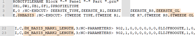
The $BASIS variable must be replaced with $MBASIS. $MBASIS is the length between the profile's start and end base points, and is needed to get the extra length measured from the profile base points.
-
Variables $EERSTE_OL and $TWEEDE_OL must be added. These are needed to get the extra length defined in the type file to the sketches. If the value of an extra length variable is zero, the value will not be shown in the profile sketch.
$FIRST_OL and $SECOND_OL can be used instead of $EERSTE_OL and $TWEEDE_OL. However, the result will be different in the profile sketch:
-
$FIRST_OL and $SECOND_OL – When the variable value is zero, the extra length text (prefix) defined in the sketch layout is shown (the value is not shown).
-
$EERSTE_OL and $TWEEDE_OL – When the variable value is zero, the the extra length text (prefix) defined in the sketch layout is not shown (the value is not shown).
-
-
The $AANSLAG_MARK1_LENGTE and $AANSLAG_MARK2_LENGTE variables must be replaced with $M_BASIS_MARK1_LENGTH and $M_BASIS_MARK2_LENGTH, respectively. These are needed to make the end marking indications start from the profile's base points instead of the extreme points of the end shapes.
Additional bend length for bent profiles
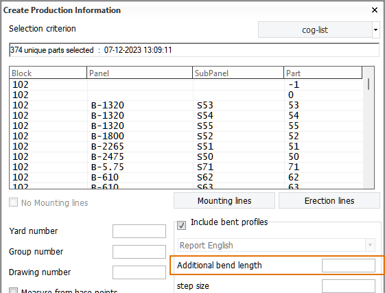
It is possible to define additional bend length for bent profiles when generating production information. This can be done by entering the desired value for Additional bend length in the Create Production Information dialog.
When generating profile sketches and robot files for bent profiles, by default the system includes the profile end type length in the user-defined additional bend length. In this case the total bend length is measured from the profile's base point.
Instead of the default behavior, it is possible to have the system add the user-defined additional bend length to the end type length when it calculates the total length of the profile. This can be done by changing the value of the Bend Length Calculation setting in System Management > Production > Profile Sketch > Settings from its default value of Yes to No.
The image below illustrates the difference between the two options in measuring the additional bend length.
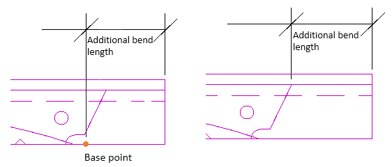
Left: Additional bend length includes end type length (setting value Yes).
Right: Additional bend length added to end type length (setting value No).