Profiles' molded side handling
The molded side placement and the molded side handling settings of profiles together affect how the profile marking lines appear on the production information of plates. This true for shell frames as well.
- There are three options for the Molded Side Placement setting available when creating or modifying profiles: Default, Center, and Base width. These settings allow you to choose how the profile is aligned with another construction item that is located on the other side of the plate. See Molded side placement below.
- With the Molded Line Handling setting you can choose how profiles are marked in coded plates: using the standard presentation, or using user-defined symbols. These presentation types also handle profile marking lines and symbols slightly differently. See Molded side handling below for the details.
Molded side placement
By default the profile is aligned with the other construction item by the molded side of the profile. The profile can also be aligned by the midpoint of the profile body thickness or width, or by the profile's thickness side. The image below shows the three available options:
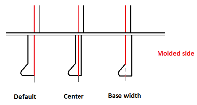
- Default – Alignment by the molded side.
- Center – Alignment by the midpoint of profile thickness or width.
- Base width – Alignment by the thickness side (at full thickness or width).
See Direction for more information on these settings.
Molded side handling
The Molded Side Handling setting is located in the System Management application, Production > Plate Cutting Data > Marking > Profiles.
Standard behavior option
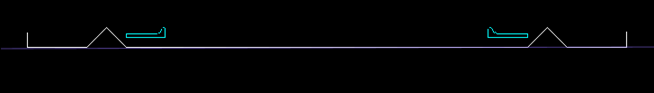
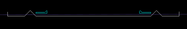
This presentation type is the default option. Standard profile symbols are used, and the profile symbol has an offset from the marking line. The result on the coded plate with the different molded placement options is as follows:
-
Default – The profile marking line is at the position where the profile was created.
-
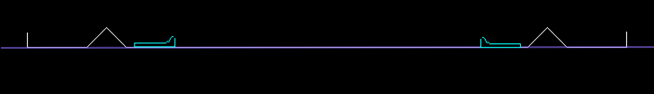
Center – The profile marking line is shifted by half the thickness of the profile's base width in the direction opposite to the thickness indication.
-
Base width – The profile marking line is shifted by the full thickness of the profile's base width in the direction opposite to the thickness indication.
Using user defined symbols option
User-defined profile symbols are used, and the profile symbol is placed so that its origin is on the profile marking line without any offset. The user-defined profile symbols must be placed in the project's norms directory, %NCGNORMS%/details/, see Profile symbols location and naming below.
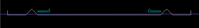
The result on the coded plate with the different molded placement options is as follows:
-
Default – The profile marking line is at the position where the profile was created. Same as the standard behavior but the profile symbol has no offset from the marking line.
 Show/hide image

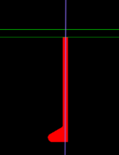
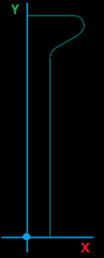
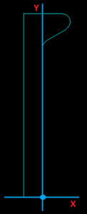
The picture below is an example of a user-defined symbol for bulb profile:
-
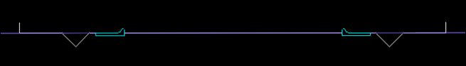
Center – The profile marking line is shifted by half the thickness of the profile's base width in the direction opposite to the thickness indication. Same as the standard behavior but the profile symbol has no offset from the marking line.
-
Base width – The profile marking line is at the position where the profile was created, but the thickness indication is on the opposite direction, and also opposite to the marking line end flags.
(Show/hide image

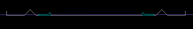
The picture below is an example of a user-defined symbol for bulb profile. Note that the origin is at a different location than with the Default option.
Profile symbols location and naming
The user-defined profile symbols must be placed in the project's norms directory, %NCGNORMS%/details/.
The naming of the profile symbol model files must be as follows:
- For the Default and Center options: tanmodelmsp%proftype%.mod
- For the Base width option: tanmodelmspbw%proftype.mod
For example, for the profile type bulb [401]:
- tanmodelmsp401.mod, and
- tanmodelmspbw401.mod
Note: If the profile symbol model files are missing from the project, a 1:1 profile section is generated and placed on the marking line, without offset from the marking line, and with the origin on the thickness side of the profile.
Note: If a profile symbol model file exists but has no content (it is an empty model), no profile symbol will be shown for the profile marking line.