Shell frame bending lines in profile sketches
There are three methods of presenting the shell frame bending on profile sketches:
- Standard presentation – The shell frame bending is presented as one or more bending lines.
- Inverse curve of profile – The shell frame is presented as one inverse curve line.
- Real shape curve along hull shape – The shell frame is presented as a 'real' curve line along the hull shape.
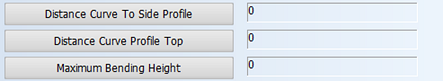
Which presentation is used depends on the values of three System Management settings in System Management > Production > Shellframe Bending List > Settings. These settings control the position of the bending lines and the maximum space allowed for them in the profile sketch. The settings are as follows:
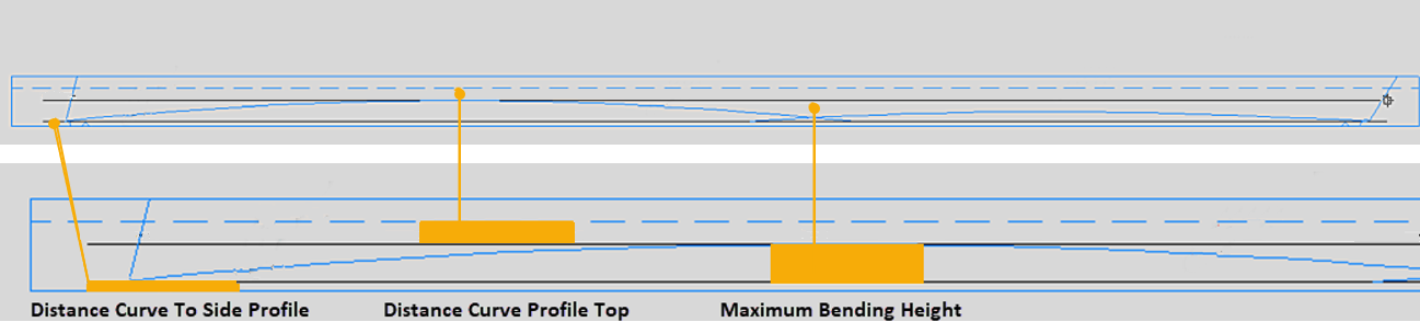
- Distance Curve To Side Profile – Sets the distance between the starting point of the bending line curve and the shell frame baseline.
- Distance Curve Profile Top – Sets the distance from the top of the bending line curve to the top of the shell frame.
- Maximum Bending Height – Sets the free space from the top of the profile to the top of the bending line curve, and thus limits the maximum height of the curve.
The following sections describe each of the presentation methods, and which setting values to use to get the desired result.
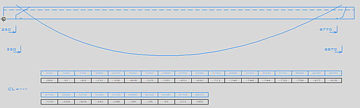
Standard presentation
In the standard presentation of shell frame bending lines, the shell frame is presented as one or more bending line curves, and the maximum height of the curve is the shell frame's body height * 0.8.
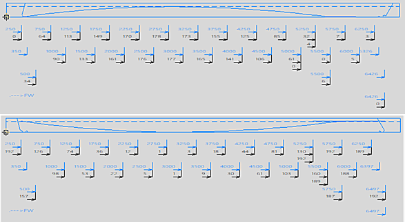
The bending information can also be shown in a table at the bottom of the sketch if so desired:
The system creates tables of at most two rows, below each other.
- If small overlap steps for bending line curves are used, the Table text size should be set smaller (Production > Profile Sketch > Sketch Layout – General Settings).
When the shell frame contains cutouts or holes, the table is usually the more descriptive way to present the bending information.
The table will be included in the profile sketch if Bending Table is selected in the Create Production Information dialog.
System Management setting values for the standard presentation
Production > Shellframe Bending List > Settings
For the standard presentation of shell frame bending lines, use 0 as the value for all of the related settings. Zero is also the default value for each of the settings.
Inverse curve of profile
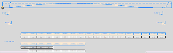
The inverse curve line is presented outside of the shell frame body when the shell frame has a large curve. The profile length is calculated over the shell frame's neutral line (before deformation from straight to curved). This is to get the best possible positions for holes and cutouts, because the positions of the holes and cutouts is relative to the neutral line.
System Management setting values for the profile inverse curve presentation
Production > Shellframe Bending List > Settings
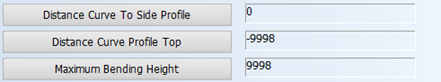
For presenting the shell frame bending lines as inverse curves, use the following settings:
- Distance Curve to Side Profile – A positive value (instead of 0) leads to a smaller height of the inverse curve line. Do not use a value larger than half of the shell frame height.
- Distance Curve Profile Top – Set to a negative value in the range of −3000...−9998. A value between −3000 and 0 is interpreted as 0.
- Maximum Bending Height – Set to a positive value with a maximum of 9998.
The first two settings are used to calculate the maximum height of the inverse bending curve. The basis is 0.8 * shell frame height.
In the end the maximum height of the inverse curve lines will be:
0.8 * shell frame height − the value of Distance to Side Profile − the value of Distance Curve Profile Top
The Maximum Bending Height setting can be used to make the height smaller than the calculated height. The Maximum Bending Height value will be used regardless of the values of Distance Curve to Side Profile and Distance Curve Profile Top.
Real shape curve along hull shape
The sketch presents the shell frame's 'real' curve along the hull shape line instead of the standard or inverse curve presentation. The profile length is the real length along the hull line (length after bending). The positions of holes and cutouts are relative to the shell frame base line.
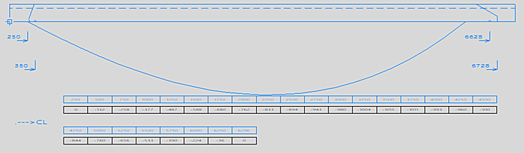
The bending line is the representation of the real shape, while the profile in the sketch is presented as straight. This is why the bending line does not extend to ends of the profile.
The position of cutouts, holes and marking lines will be along the base line of the sketch.
System Management setting values for the real shape curve presentation
Production > Shellframe Bending List > Settings
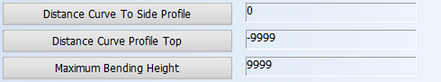
- Distance Curve to Side Profile – Set to 0.
- Distance Curve Profile Top – Set to -9999.
- Maximum Bending Height – Set to 9999.