Straight profiles and face plates
To be able to create plate cutting data for straight profiles and face plates with the Production > Create Production Information function the following data is needed:
Robot layout
A special robot layout file named dxfrobot.ind should be created in the %ncgnorms% folder.
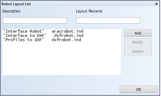
Robot layout selection list
With the System Management application function Production > Robot Files > Settings > Robot Layout List, you need to add the dxfrobot.ind as the layout file name with a suitable description such as Profiles to DXF.
Endtype detail models
The detail models to be presented in the Profile List Sketch should be placed in the %ncgnorms%\details folder. Usually for each endtype you have a LDT<detailno.>.mod (endtype is at the left-hand side of the profile) and a RDT<detailno.>.mod (endtype is at the right-hand side of the profile).
These models can be modified by opening them using the function File > Open Model, then use the standard 2D drafting functions and then save the model with the File > Save Model or Save Model As... function with the same name or a new name.
Detail indication in the endtype typefiles
The 'R' line in the endtype typefile should be used to indicate which <detailno.> should be used for the endtype. See Norms Type Files > Export Data to Production Information in Administrator's Guides.