Creating shell frames in a corner
With the 3D-Show functions Construction > Shell Frames > Fixed Angle to Shell and With Fixed Angle to Base it is possible to create shell frames in a corner without the need to define extra hull lines first.
The base of a shell frame in a corner is positioned at the intersection of two parallel lines. See the image below.
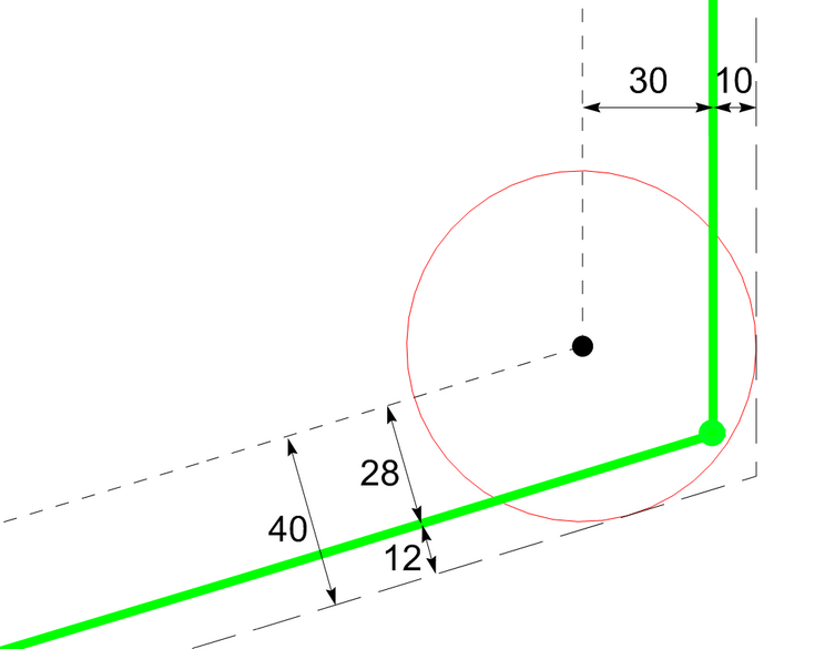
The green dot (usually a knuckle) divides the hull in an upper and a lower part. The user can specify a parallel distance for these parts separately. In the above example the values 28 and 30 are specified. For a pipe with 80 mm diameter, this results in a shell frame going into the hull by 12 mm at the lower part and by 10 mm at the upper part (useful when these are the respective shell plate thicknesses).
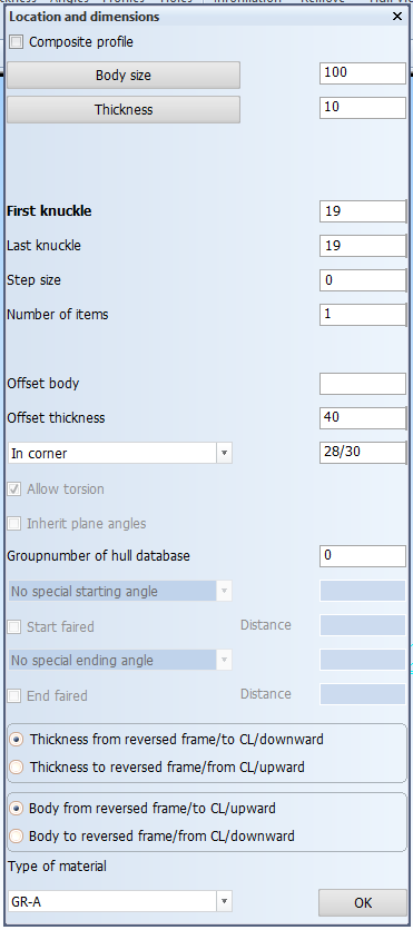
The panel above shows the input necessary for the example. The syntax 28/30 is used to specify the lower and upper distances. If they are the same, a single value is sufficient.
In case that the shell frame should be constructed in the corner between two different hull groups, a similar syntax as for the distances can be used: separate the hull groups with a '/', for example '0/1' for groups 0 and 1. The curve is assumed to lie on the first hull group.
When there are multiple possibilities to place the shell frame, that is, when the hull group doesn't end on the curve, the corner to place the shell frame can be defined by specifying the correct body and/or thickness direction:

Thickness direction standard, body direction standard

Thickness direction non standard, body direction standard

Thickness direction non standard, body direction non standard

Thickness direction standard, body direction non standard
The 3D-Contek function Modify > Shell Frames > Angles and the 3D-Show function Construction > Shell Frames Angles also provide the In corner option, so that the specified values can be adjusted.