Relating plates to shell plates in cross section
A plate can be related to a shell plate in cross section which intersects the plane of the plate, also called the calculation plane. Shell plates in cross section have precedence over hull lines during relation selection in order to allow this action. A relation to a shell plate can have the same properties as relations to other plates in cross section:
- A shell plate can be indicated at the molded or the thickness side
- A parallel distance can be added
- A complete relation (default), a 1 vector relation or an end point relation can be given
If an angle relation is defined then a shell plate cannot be indicated as its base.
When there is space between the indicated relations (shell plates) then a straight line will be used. This is the same behavior as with regular plates.
There is a difference in behavior depending on the shape group which the shell plates are in:
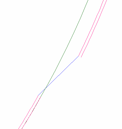
It is assumed that the plate contour follows the part with the shortest distance between the two hull lines. The intersection point between two relations is positioned at the nearest point of the second shell plate. The vector between the two ends belongs to the first relation, shown with the blue line in figure below. It is only done when both relations to the shell plates are ‘Complete’ relations. The green line represents the hull line in the image below.
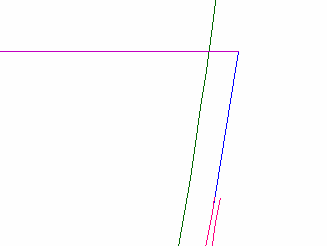
The vector at the end of the shell plate in cross section is extended to the actual area. This method is valid when then next relation is a shell plate in another group or any other relation type. The blue line in the figure below indicates the extension of the shell plate relation. The horizontal pink line is some other type of relation. This next relation can be any type of relation.
It can be that not all shell plates are created yet and the user wants to follow the hull line next to a shell plate relation. There are different actions required for two different possible situations:
- Indicate shell plate
- Indicate shell plate at the end of the shell plate and select ‘End relation’ instead of ‘Complete relation’
- Select hull line
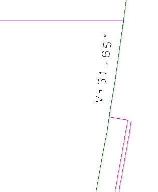
The result of these actions is shown below. The lower pink line is the relation perpendicular to the shell plate.
- Indicate hull line
- Indicate shell plate at the end of the shell plate and select ‘End relation’ instead of ‘Complete relation’
- Select the shell plate
The transition line between the end of the shell plate to the shape is perpendicular to the end of the shell plate.