Examples
The examples below illustrate how the contour of plates can be specified in some specific situations.
The first example shows a plate, which could have been a bracket. The combination of a circle on a cross-over is explained here.
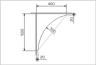
The plate in this example has a width of 400 mm, height of 500 mm noses of 20 mm and a radius of 500 mm. Figure below shows this plate. After entering the thickness and type of material, the contour needs to be defined counter clockwise. It does not matter which is the first relation. Here we start at the top.
Relations sequence
- Indicate the deck.
- Indicate the bulkhead.
- Indicate the deck, then enter 500 as parallel distance.
- Indicate the bulkhead, then enter a parallel distance of 20 (nose below). Indicate that a cross-over is following. The crossover is presented as the dashed line in figure below. The circle is left of this line. So, enter the radius (500) and choose Left instead of Cutout.
- Indicate the deck, then enter 20 as parallel distance.
- Indicate the bulkhead, then enter a parallel distance of 400.
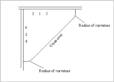
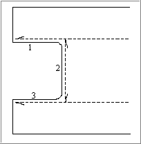
The second example shows a cross-over precede with a radius of curvature and followed by a radius of curvature. The examples shows when these radii are to be entered.
- Indicate the deck.
- Indicate the bulkhead.
- Indicate the deck, then enter a parallel distance (height of the plate), then enter the first radius.
- Indicate the bulkhead, then enter a parallel distance (height of the nose below) and choose cross-over.
- Indicate the deck, the enter a parallel distance (height of the upper nose), then enter the radius.
- Indicate the bulkhead, the enter a parallel distance (plate width).
Now, the contour has been defined completely. So the "OK" button can be pressed. Figure below shows the plate. The numbers below are shown in this figure at the side at which the deck and the bulkhead are indicated.
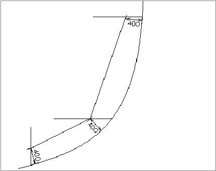
The third example shows a plate which seems to have two sequential relations to the same hull line and which has a kink in the contour. The distance of the contour is only known at the beginning and end of these relations, in this example 400 mm, see figure below. The contour can be defined as following.
- Indicate the hull line.
- Indicate the upper deck.
- Indicate the hull line, then enter 400 as parallel distance and also 400 as second parallel distance.
- Indicate the horizontal line at the centre of the figure (this can be a deck).
- Indicate the hull line, then enter 400 as parallel distance and also 400 as second parallel distance.
- Indicate the bulkhead below.
Now, the contour has been defined completely. So the OK button can be clicked.
The next example shows a plate which is related to profile on a plate in plan view. This situation will happen mainly when defining a topological arbitrary hole. However, a plate can be split into two plates and need these relations too. In this example radii of curvatures are used. Figure below shows the example. Three relations of this figure are explained below.
- Indicate the upper profile in bulb view, then enter a parallel distance. The text cutout within the panel jumps to radius of curvature automatically. Enter the size of the radius of curvature.
- Indicate the vertical profile in bulb view, enter the parallel distance, enter the size of the radius.
- Indicate the lower profile in bulb view and enter the parallel distance.
- Indicate another relation if needed, etc.
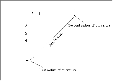
The next example shows the relation angle from together with radii of curvature. Figure below shows such an angle from relation which is preceded by a radius of curvature and followed by a radius of curvature. The point is when to enter these radii.
- Indicate the deck.
- Indicate the bulkhead.
- Indicate the deck, enter a parallel distance (plate height), indicate the size of the radius of curvature.
- Indicate the bulkhead, enter a parallel distance (height of the lower nose). Now choose the option angle from, enter the angle and press the enter key. Also, the size of the second radius of curvature needs to be entered now.
- Indicate the bulkhead, enter a parallel distance (width of the plate).
The contour has been defined completely now, so click the OK button. The numbers mentioned above show in figure below at which side the deck and bulkhead are indicated.
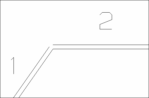
The following example applies for a relation between the edges of two plates in cross section. The following steps must be taken in order to ensure that the proper rules for applying bevels in plan view are referenced even though the individual plates are being viewed in cross section. This will allow both of the plates to have a bevel applied to their edge while still allowing the user to view the plates clearly. An example arrangement of two plates, which would benefit from this process, can be seen in the image below the steps.
- Create plate 1.
- Create plate 2 and relate plate 2 to plate 1.
- Relate plate 1 to plate 2.
- Recalculate plate 2.