Min./Max. relations
Min. Breadth
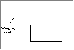
This button enables you to specify a local minimum breadth value, which means that the plate material will be located to the right of this line. Instead of a fixed value in mm this can also be a grid value. You can also select a grid line from the graphical window. When the minimum breadth has been accepted, the program will draw a line on this breadth, and will do so once you have indicated another relation. The value will remain in the input box until you click on this button or the Shape button next to it. You can therefore enter a local minimum breadth several times (see the example in image below).
Min. Shape
Clicking this button when working on a cross-section means that the hull line will be located on the port side. The default is hull group 0. This button is only useful in the 3D-Show application when creating orthogonal plates, because in that case the default is 'no hull line shown'. If the hull line in question is present in the drawing, you are advised to use it.
Min. Height
With this button you can indicate a local minimum height value, which means that the plate material will be located above this line. You can also select a grid value or grid line. For the rest this button functions as the Min. Breadth button.
Min. Shape
Clicking this button when working on a cross-section means that both the starboard and the port sidehull lines will be selected, in that order of sequence. The default is hull group 0. If these hull lines are present in the drawing, you are advised to use them.
Max. Breadth
With this button you can indicate a local maximum breadth value, which means that the plate material will be located to the left of this line. Instead of a fixed value you can also enter a grid value. A grid line can be selected in the graphical window with the right mouse button. For the rest, this button functions as the Min. Breadth button.
Max. Shape
Clicking this button for a cross-section means that the hull line will be located on the starboard side. The default is hull group 0. If the hull line in question is present in the drawing, you are advised to use it.
Max. Height
With this button you can indicate a local maximum height value, which means that the plate material will be located below this line. Instead of a fixed value you can also enter a grid value. You can also select a grid line in the graphics window with the right mouse button. For the rest this button functions as the Min. Breadth button.
Max. Shape
Clicking this button when working on a cross-section means that both the port side and the starboard hull lines will be selected, in that order of sequence. The default is hull group 1 (usually the camber). If these hull lines are present in the drawing, you are advised to use them.