Changing plate relations
By changing the plate relations you can modify the borders of the plate.
Important: When modifying plate borders, always work in a counter-clockwise direction.
Do the following:
-
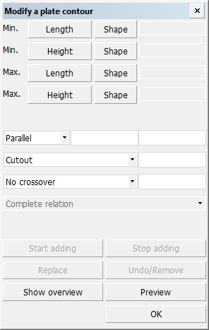
Select Construction > Plates > Modify > Relations. Then select the plate. The Modify a plate contour dialog opens.
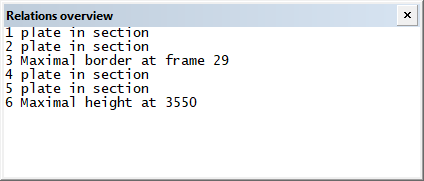
At the same time, a separate Relations overview window showing the plate relations opens.
When you select a relation in the list, the relation is highlighted in the graphical window. If a relation only has one point in common with the plate contour, only this point is highlighted. If a related part is not present anymore in the graphical window because this part has been removed, the relation number is shown in different colour (with pen 6) with a surrounding square. In the relations list this relation is marked with an asterisk.
-
Select the relation to modify. You can select the relation either in the graphical window or in the relation list.
You can remove unnecessary or incorrect relations by selecting it and clicking Undo/Remove in the Modify a plate contour dialog.
You can add relations after the selected relation by clicking Start adding. Click Stop adding once done. Then select the relation where the modification ends.
-
Make the desired changes in the Modify a plate contour dialog. For example, you can change the parallel distance, cutout, or the fixed limitation values.
Note: When creating a plate using a hole edge as a relation, indicate outside the hole for a parallel relation. A negative value means at the inside of the hole, and a positive value means a parallel distance outside the indicated hole.
Click Preview to see the changes applied in the graphical window. The system calculates the new contour and shows it, but the changes are not saved to the construction database.
The system applies the changes when you select another relation, but the changes are not saved to the construction database yet.
-
Click OK to save the changes in the construction database and close the dialog.
Note: If you modify a panel (plate split by seams or slots/splitters), the system will evaluate and, if necessary, adjust the positions of the bevels at the seams and slots/splitters after the modifications. The system may also may also remove bevels.
Examples
The following two examples illustrate cases where the plate borders are modified by changing the plate's relations.
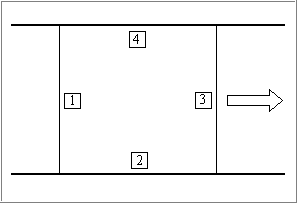
Example 1: Plate is given greater breadth
The plate should be given a slightly greater breadth. This is done by selecting the number 3 relation and then entering a new, greater Max. Breadth value.
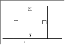
Example 2: Cutting off part of the plate
The plate is defined by two decks and a minimum and maximum breadth value. We want to cut off a part from the middle of the plate contour.
In the picture below, the starting situation is shown on the left, and the end situation is on the right.
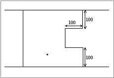
Procedure:
- Select relation 3. The relation is highlighted in the graphical window and in the relations list.
- Click Start adding.
- Select the lower deck in the graphical window, and enter a Parallel value (100 in this example).
- Enter a Max. Breadth value (smaller than the old value, 100 in this example).
- Select the upper deck, and enter a Parallel value for this deck also (100 in this example).
- Click Stop adding. The relation where the modification started is added at the end of the list.
- Select the ending relation in the graphical window, or select the highlighted relation in the relations list.
- Click Preview for a preview. If you are certain of the result you can skip the step.
- Click OK if you are satisfied with the result.